
Machining device for stamping bearing with counterbore

A processing device and bearing technology, applied in metal processing equipment, forming tools, manufacturing tools, etc., can solve the problems of increasing structural strength, poor forming of stamping parts, poor assembly limit, etc., to improve stability and reduce bending deformation effect

Pending Publication Date: 2021-04-06
宁波三耐机械有限公司
View PDF0 Cites 0 Cited by
  • Summary
  • Abstract
  • Description
  • Claims
  • Application Information

AI Technical Summary

Problems solved by technology

[0002] Stamping bearings are widely used and can withstand radial loads and bidirectional axial loads. Usually, the structure of stamping bearings includes outer rings, inner rings, cages and stamping bodies. Among them, the stamping bodies are the core components of stamping bearings. The stamping bearing provides the installation position and increases the structural strength. A stamping bearing in the prior art has a stamping body sleeved outside the outer ring, and the stamping parts and the outer ring are not tightly matched. During use, the bearing is prone to axial displacement. In addition, a processing device for stamping bearings in the prior art usually directly stamps the stamping parts on the bearing, the forming of the stamping parts is not good, and the assembly limit between the stamping parts and the outer ring of the bearing is not good. good

Method used


Image

  • Machining device for stamping bearing with counterbore
  • Machining device for stamping bearing with counterbore
  • Machining device for stamping bearing with counterbore

Examples


Embodiment Construction

[0028] The following will clearly and completely describe the technical solutions in the embodiments of the present invention with reference to the accompanying drawings in the embodiments of the present invention. Obviously, the described embodiments are only some, not all, embodiments of the present invention. Based on the embodiments of the present invention, all other embodiments obtained by persons of ordinary skill in the art without making creative efforts belong to the protection scope of the present invention.

[0029] It will be understood that although the terms upper, middle, lower, top, end, etc. may be used herein to describe various elements, these elements should not be limited by these terms. These terms are only used to distinguish elements from each other for ease of understanding, and are not used to define any directional or sequence limitation.

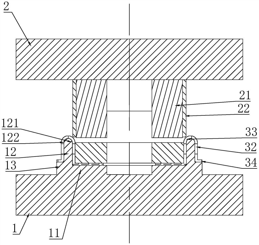
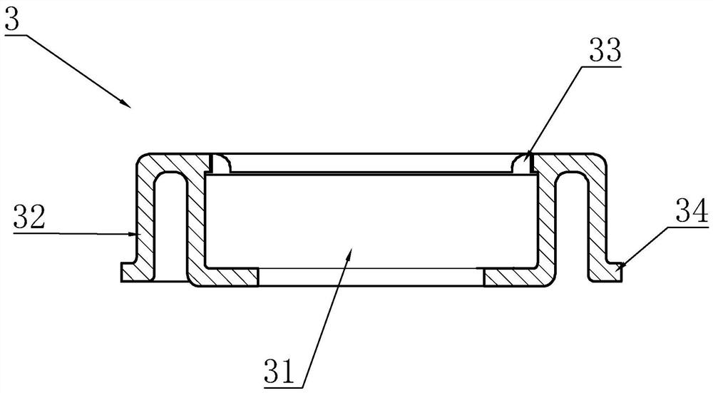
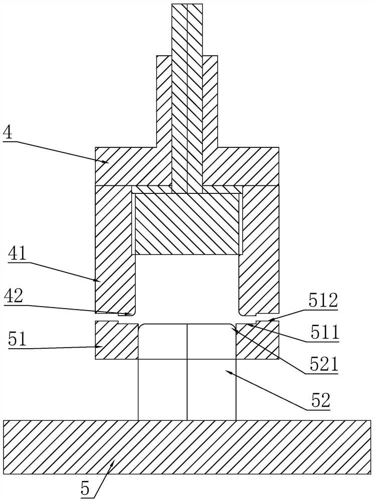
[0030] Such as Figure 1-7 As shown, a processing device for a stamping bearing with a lock, including a bear...


PUM

PropertyMeasurementUnit
Outer diameteraaaaaaaaaa

Abstract

The invention discloses a machining device for a stamping bearing with a counterbore. The machining device comprises the bearing, a stamping base arranged outside the bearing in a sleeving mode and a machining device body used for forming the stamping base and installing the stamping base into the bearing, a cavity allowing the bearing to be placed in is formed in the stamping base, a forming base is formed on the periphery of the stamping base through stamping, the forming base is arranged in a U shape with a downward opening, the bottom of the forming base is higher than the bottom of the stamping base, the machining device body comprises a riveting die, axial movement of the outer ring of the bearing is limited, and the assembling stability of the stamping base and the bearing is improved.

Description

technical field [0001] The invention relates to the technical field of bearing equipment, in particular to a processing device for stamping bearings with locking ports. Background technique [0002] Stamping bearings are widely used and can withstand radial loads and bidirectional axial loads. Usually, the structure of stamping bearings includes outer rings, inner rings, cages and stamping bodies. Among them, the stamping bodies are the core components of stamping bearings. The stamping bearing provides the installation position and increases the structural strength. A stamping bearing in the prior art has a stamping body sleeved outside the outer ring, and the stamping parts and the outer ring are not tightly matched. During use, the bearing is prone to axial displacement. In addition, a processing device for stamping bearings in the prior art usually directly stamps the stamping parts on the bearing, the forming of the stamping parts is not good, and the assembly limit bet...

Claims


Application Information

Patent Timeline
IPC IPC(8): B21D37/10B21D39/00B21D53/10
CPCB21D37/10B21D39/00B21D53/10
Inventor 虞文锋
Owner 宁波三耐机械有限公司
Learn More