
A combination fixture for drill bit production and processing

A combination fixture and drill clamp technology, which is applied in the direction of manufacturing tools, metal processing equipment, metal processing machinery parts, etc., can solve the inconvenient operation of drill clamping and disassembly, affect the quality and efficiency of drill bit processing, and cannot meet the requirements of drill bit processing Requirements and other issues to achieve the effect of facilitating processing or inspection, improving service life and working reliability, and preventing wear and corrosion

Active Publication Date: 2022-04-08
苏州曼威精密工具有限公司
View PDF9 Cites 0 Cited by
  • Summary
  • Abstract
  • Description
  • Claims
  • Application Information

AI Technical Summary

Problems solved by technology

[0002] In the center processing technology, the drill bit is a tool used for cutting and drilling. It works by fixing the drill bit holder. The drill bit holder can stabilize the drill bit and keep the drill bit at the corresponding processing position according to the production and processing needs, so as to improve work efficiency and precision, but the existing ordinary fixtures can no longer meet the needs of drill bit processing: on the one hand, it is inconvenient to clamp and disassemble the drill bit; on the other hand, it is inconvenient to adjust the drill bit according to the needs It is not easy to adjust the position of the drill to meet different processing requirements for the drill on the same fixture, thus affecting the processing quality and efficiency of the drill

Method used


Image

  • A combination fixture for drill bit production and processing
  • A combination fixture for drill bit production and processing
  • A combination fixture for drill bit production and processing

Examples


Embodiment Construction

[0027] Specific embodiments of the present invention will be described below in conjunction with the accompanying drawings.

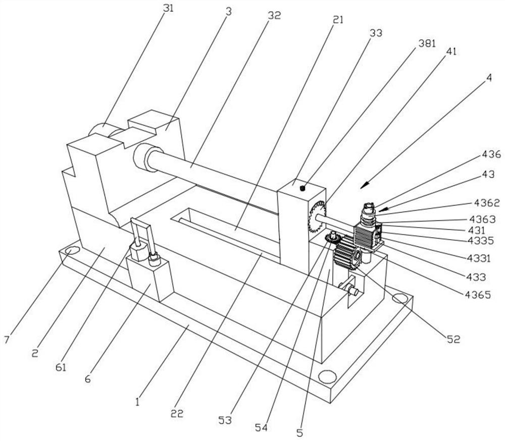
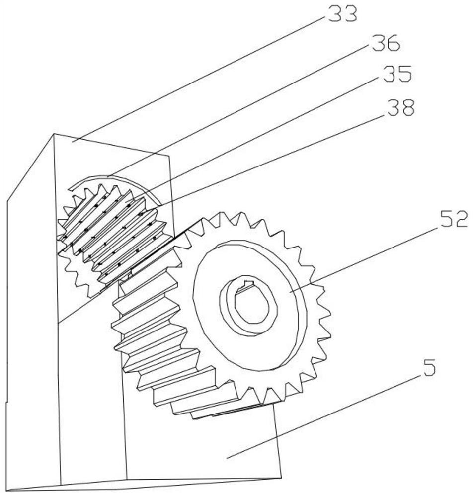
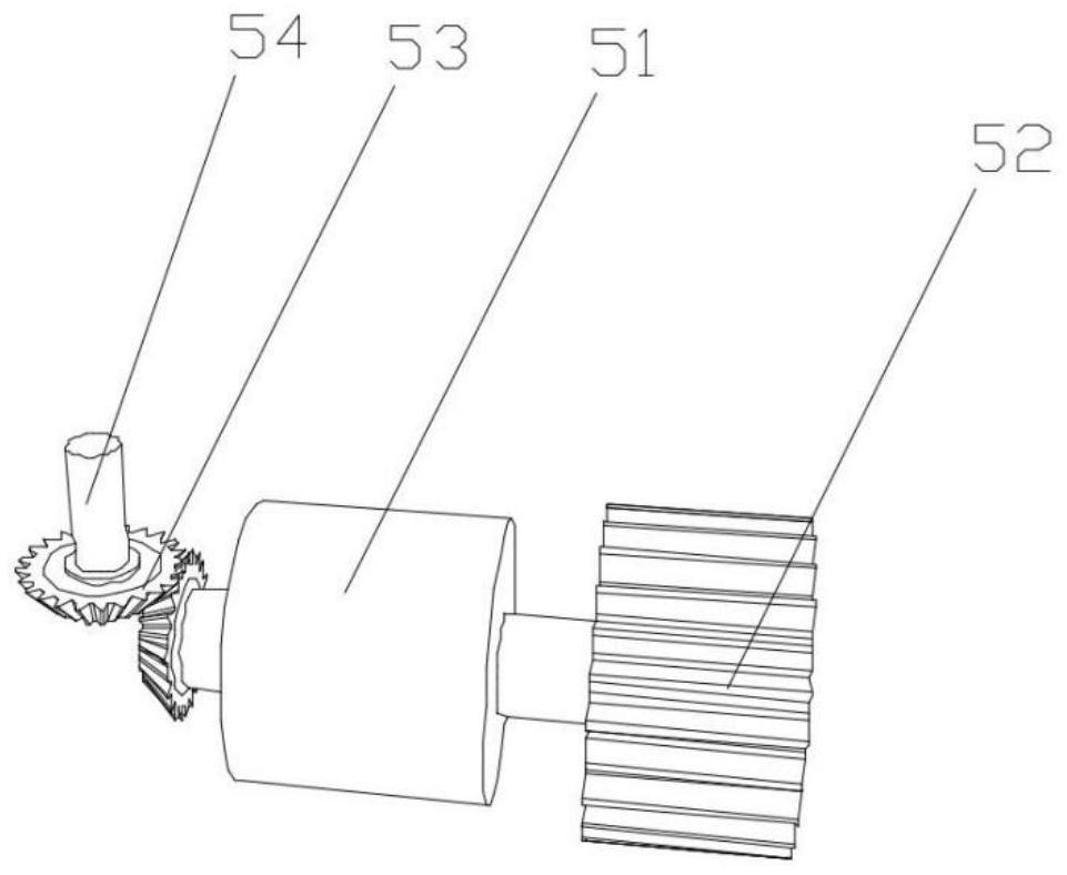
[0028] Such as Figure 1-10 As shown, it is a combination fixture for drill bit production and processing in this embodiment, including a fixture seat 1, a clamping table 2 is fixedly arranged on the fixture seat 1, and a cylinder seat 3 is provided at one end of the top surface of the clamping table 2. 3 is fixedly provided with a cylinder 31, the piston rod of the cylinder 31 is coaxially provided with a connecting shaft 32, and the first end of the connecting shaft 32 is fixedly arranged on the piston rod of the cylinder 31, and the second end of the connecting shaft 32 is fixedly provided with The angle adjustment seat 33, the second end of the connecting shaft 32 is provided with a positioning shaft hole 34, the other end of the top surface of the clamping table 2 is provided with an adjustment groove 21, and the bottom of the angle adjustment seat 3...


PUM


Abstract

The invention provides a combination fixture for drill bit production and processing, which relates to the technical field of drill bit processing equipment, and includes a fixture seat, a clamping table is fixedly arranged on the fixture seat, and a cylinder seat is arranged on one end of the top surface of the clamping table, and the cylinder seat is fixedly arranged There is a cylinder, the piston rod of the cylinder is coaxially provided with a connecting shaft, and the first end of the connecting shaft is fixedly arranged on the piston rod of the cylinder, the second end of the connecting shaft is fixedly provided with an angle adjustment seat, and the second end of the connecting shaft The end is provided with a positioning shaft hole, and the other end of the top surface of the clamping table is provided with an adjustment groove. The bottom of the angle adjustment seat is located in the adjustment groove, and a guide rod is fixed in the adjustment groove. The length direction of the adjustment groove is the same as that of the guide rod. The guide rod moves through the bottom of the angle adjustment seat, and the angle adjustment seat is slidably arranged in the adjustment groove. The invention has the advantages of being convenient for clamping and fixing the drill bit during processing, and can adjust the position of the drill bit according to the processing requirements.

Description

technical field [0001] The invention relates to the technical field of drill bit processing equipment, in particular to a combined fixture for drill bit production and processing. Background technique [0002] In the center processing technology, the drill bit is a tool used for cutting and drilling. It works by fixing the drill bit holder. The drill bit holder can stabilize the drill bit and keep the drill bit at the corresponding processing position according to the production and processing needs, so as to improve work efficiency and precision, but the existing ordinary fixtures can no longer meet the needs of drill bit processing: on the one hand, it is inconvenient to clamp and disassemble the drill bit; on the other hand, it is inconvenient to adjust the drill bit according to the needs It is not easy to adjust the position of the drill to meet different processing requirements for the drill on the same fixture, thus affecting the processing quality and efficiency of t...

Claims


Application Information

Patent Timeline
Patent Type & Authority Patents(China)
IPC IPC(8): B23Q3/08
CPCB23Q3/08B23Q2703/04B23Q2703/10
Inventor 赵家兵
Owner 苏州曼威精密工具有限公司
Learn More