Plastic cylinder cutting equipment for plastic machining
A cutting equipment and plastic technology, applied in metal processing and other directions, can solve the problems of no plastic cylindrical cutting equipment and single function, etc.
- Summary
- Abstract
- Description
- Claims
- Application Information
AI Technical Summary
Problems solved by technology
Method used
Image

Examples
specific Embodiment approach 1
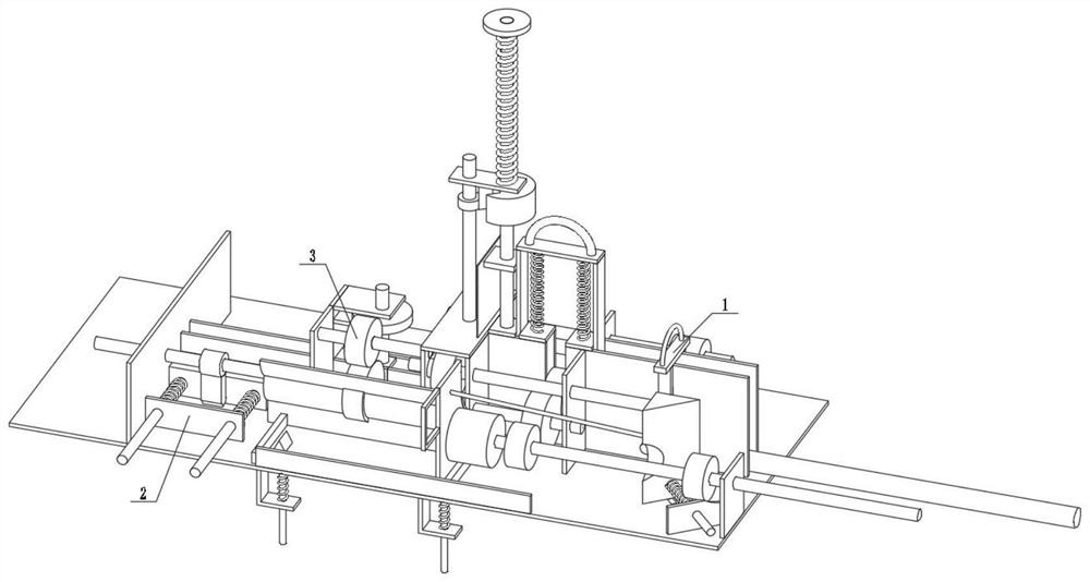
[0030] Combine below figure 1 , figure 2 , image 3 , Figure 4 , Figure 5 , Image 6 , Figure 7 , Figure 8 , Figure 9 , Figure 10 , Figure 11 , Figure 12 , Figure 13 , Figure 14 , Figure 15 To illustrate this embodiment, the present invention relates to a sampling device, more specifically a plastic cylinder cutting device for plastic processing, including a transmission rotation linkage mechanism 1, an intermittent cutting linkage mechanism 2, and a spherical cutting mechanism 3. The equipment can The plastic cylinder is conveyed and rotated, the equipment can cut the plastic cylinder into shorter cylinders when the plastic cylinder is conveyed and rotated, the equipment can convey the shorter cylinders into the collection box, and the equipment can cut the plastic cylinder into small balls.
[0031] The transmission rotation linkage mechanism 1 is connected with the intermittent cutting linkage mechanism 2, the intermittent cutting linkage mechanism ...
specific Embodiment approach 2
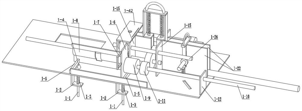
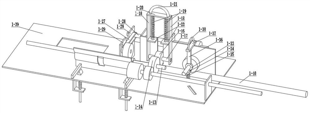
[0033] Combine below figure 1 , figure 2 , image 3 , Figure 4 , Figure 5 , Image 6 , Figure 7 , Figure 8 , Figure 9 , Figure 10 , Figure 11 , Figure 12 , Figure 13 , Figure 14 , Figure 15 Describe this embodiment. This embodiment will further explain Embodiment 1. The transmission rotation linkage mechanism 1 includes a reset column 1-1, a reset connection block 1-2, a reset tension spring 1-3, and a limit triangle block 1- 4. Limiting bar 1-5, sliding plate 1-6, handle 1-7, motor sliding limiting plate 1-8, motor 1-9, motor shaft 1-10, friction wheel 1-11, connecting plate a1- 12. Connecting shaft a1-13, friction wheel a1-14, connecting plate b1-15, friction wheel b1-16, connecting shaft b1-17, connecting plate c1-18, limit spring 1-19, connecting plate d1-20 , handle a1-21, connecting plate e1-22, connecting plate f1-23, small friction wheel 1-24, large friction wheel 1-25, connecting shaft c1-26, belt 1-27, connecting shaft d1-28, connection Pla...
specific Embodiment approach 3
[0035] Combine below figure 1 , figure 2 , image 3 , Figure 4 , Figure 5 , Image 6 , Figure 7 , Figure 8 , Figure 9 , Figure 10 , Figure 11 , Figure 12 , Figure 13 , Figure 14 , Figure 15Describe this embodiment, this embodiment will further explain the first embodiment, the intermittent cutting linkage mechanism 2 includes the linkage friction wheel a2-1, the transmission shaft a2-2, the linkage friction wheel b2-3, and the bearing connecting plate 2-4 , special-shaped friction wheel 2-5, transmission shaft b2-6, torsion spring 2-7, mounting plate a2-8, mounting plate b2-9, cutting knife 2-10, mounting plate c2-11, cutting knife limit bar 2 -12, output connection wheel 2-13, output toggle block 2-14, output sliding block 2-15, output reset shaft 2-16, mounting plate d2-17, linkage extension spring 2-18, output connection box 2- 19. The installation plate e2-20, the linkage friction wheel a2-1 is frictionally connected with the belt 1-27, the linkag...
PUM
 Abstract
Description
Claims
Application Information
 - R&D Engineer
- R&D Manager
- IP Professional
- Industry Leading Data Capabilities
- Powerful AI technology
- Patent DNA Extraction
Browse by: Latest US Patents, China's latest patents, Technical Efficacy Thesaurus, Application Domain, Technology Topic.
© 2024 PatSnap. All rights reserved.Legal|Privacy policy|Modern Slavery Act Transparency Statement|Sitemap