Logistics storage rapid unloading device and method

An unloading device and fast technology, applied in the field of storage and transportation, can solve the problems of inability to clamp and protect, and achieve the effects of convenient operation, preventing shaking and falling off, and reducing manual handling

Inactive Publication Date: 2021-04-06
哈尔滨铭川运输有限公司
View PDF6 Cites 0 Cited by
  • Summary
  • Abstract
  • Description
  • Claims
  • Application Information

AI Technical Summary

Problems solved by technology

However, this device cannot clamp and protect the goods to b...

Method used


Image

  • Logistics storage rapid unloading device and method
  • Logistics storage rapid unloading device and method
  • Logistics storage rapid unloading device and method

Examples


specific Embodiment approach 1

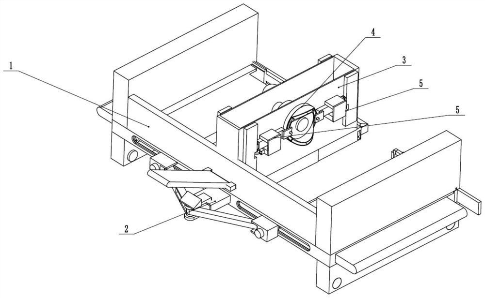
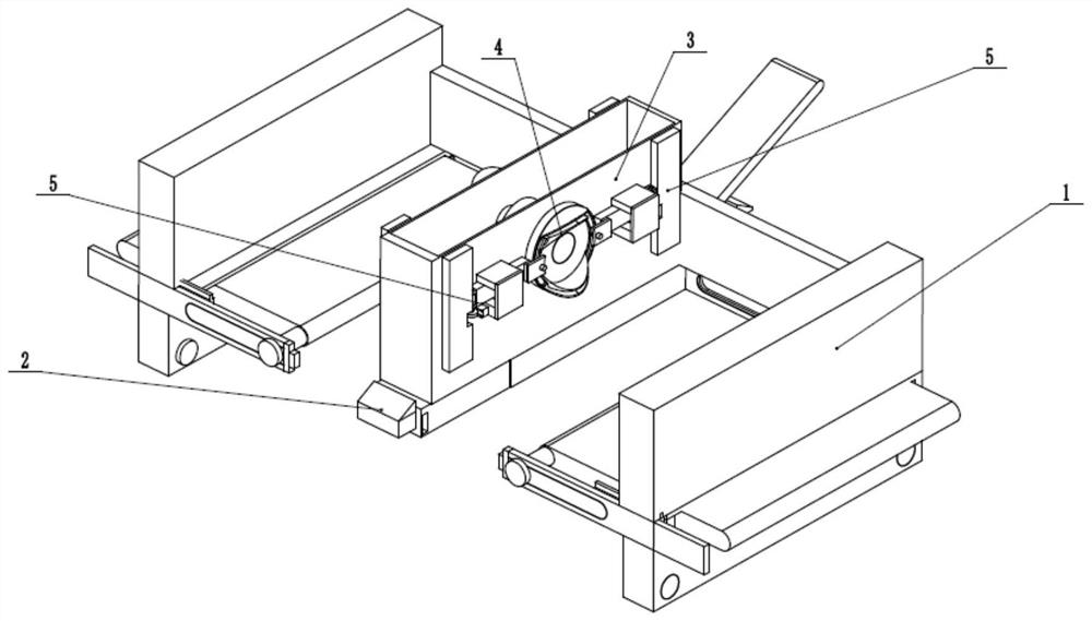
[0032] Such as Figure 1 to Figure 10 As shown, a fast unloading device for logistics storage includes a transport pull frame 1, a pedal unloading transfer device 2, a central fixed frame 3, a clamping driver 4 and four transport clamps 5, and the pedal unloading transfer device The device 2 is slidably connected to the lower end of the transport frame 1, the central fixed frame 3 is fixedly connected to the middle end of the transport frame 1, the pedal unloading transmitter 2 is engaged with the clamping driver 4 for transmission, and the clamping driver 4 is connected in rotation In the central fixed frame 3, four transport clamps 5 are evenly slidably connected in the clamping driver 4, and the four transport clamps 5 are all engaged with the central fixed frame in 3 directions for transmission. Place the goods to be transported and stacked on the transport pull frame 1 and the pedal unloading conveyor 2, and transport them to the designated position by pulling the transpo...

specific Embodiment approach 2

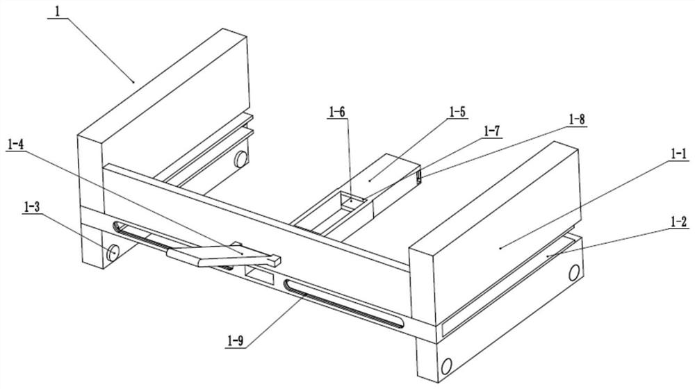
[0034] Such as Figure 1 to Figure 10As shown, this embodiment will further explain Embodiment 1. The transport pull frame 1 includes a pull frame 1-1, two side unloading plate chutes 1-2, four bottom wheels 1-3, and hinged pull rods. 1-4, center fixing seat 1-5, center rack chute 1-6, through connecting groove 1-7, two support slots 1-8 and two unloading shaft chute 1-9, two side unloading The plate chute 1-2 runs through the lower side of the two ends of the trolley frame 1-1, the four bottom wheels 1-3 are evenly rotated and connected to the lower end of the trolley frame 1-1, and the hinged pull rods 1-4 are hinged on the trolley. The rear end of the frame 1-1, the central fixed seat 1-5 is fixedly connected to the center of the inner end of the trolley frame 1-1, and the center rack chute 1-6 runs through the front and rear of the trolley frame 1-1 and the central fixed seat 1 On -5, the through communication groove 1-7 is set at the middle end of the central fixing base...

specific Embodiment approach 3

[0036] Such as Figure 1 to Figure 10 As shown, this embodiment will further explain the second embodiment. The pedal unloading transmitter 2 includes a pedal plate 2-1, a V-shaped hinged rod 2-2, a central drive rack 2-3, two hinged Seat 2-4, two unloading shafts 2-5, two unloading plates 2-6, two front connecting slide plates 2-7, two front connecting insert plates 2-8 and back pedal 2-9, pedal plate 2-1 is fixedly connected to the upper end of the V-shaped articulated rod 2-2, and the V-shaped articulated rod 2-2 is fixedly connected to the rear end of the central driving rack 2-3 through a hinged fixing seat, and the central driving rack 2-3 is slidably connected In the central rack chute 1-6, the two sides of the front end of the V-shaped hinged rod 2-2 are respectively hinged with two hinged seats 2-4, and the two hinged seats 2-4 are fixedly connected to the two unloading shafts 2-5 respectively. Two unloading shafts 2-5 are respectively slidably connected in two unloa...


PUM


Abstract

The invention relates to the field of warehousing and transportation, in particular to a logistics storage rapid unloading device and method. The method comprises the steps that goods to be transported and stacked are placed on a transport cart frame and a pedal unloading conveyor and are transported to a designated position by pulling the transport cart frame; while the lower end is blocked by back-treading on the pedal unloading conveyor, a clamping driver and four transport clamping devices are driven to move on a central fixing frame, and then the transported and stacked goods are clamped through the four transport clamping devices to be prevented from falling off in the transporting process; after being conveyed to the designated position, all the stacked cargoes automatically fall to the ground by treading on the pedal unloading conveyor, and meanwhile the clamping devices retract; in the process of transporting the goods to a warehouse, automatic alignment, clamping and protection are achieved, and the situation that the goods fall off due to shaking in the transporting process is prevented; and after arriving at the designated position, the stacked goods can be driven to automatically fall down, and manual carrying is reduced. The device and method are convenient to operate and convenient to use by workers in the actual transporting process.

Description

technical field [0001] The invention relates to the field of warehousing and transportation, and more specifically relates to a rapid unloading device and method for logistics warehousing. Background technique [0002] Patent No. CN201810454172.4 discloses a stretchable automatic cargo unloading device, including unloading support platform, platform extension device, night reflector, side shield, base support vertical rod, hydraulic support rod, support column, base The support cross bar, the central reinforcement bar, the limit connecting cross bar and the extension flat short board, the extension flat short board is connected in front of the unloading support platform, the lower end of the back side of the unloading support platform is connected with a platform extension device, and the platform extension device is provided with a control panel, a single-chip microcomputer is arranged in the control panel, and a display screen, a distance sensor, a height sensor, a power s...

Claims


Application Information

Patent Timeline
IPC IPC(8): B65G1/04B65G67/24B65G47/22
CPCB65G1/04B65G67/24B65G47/22
Inventor 杨凤茹
Owner 哈尔滨铭川运输有限公司
Why Eureka
Try Eureka