
A hardware door stopper

A door suction and hardware technology, applied in the hardware field, can solve the problems of increasing the replacement and maintenance cost of the door suction, increasing the difficulty and cost of the door suction, and unable to use the door suction buffer, so as to facilitate the promotion and use, reduce the installation cost, and increase the buffer capacity. Effect

Active Publication Date: 2022-05-24
博创金龙五金(温州)有限公司
View PDF10 Cites 0 Cited by
  • Summary
  • Abstract
  • Description
  • Claims
  • Application Information

AI Technical Summary

Problems solved by technology

However, if the door stopper is installed below the ground, holes need to be drilled on the indoor floor in advance, and the size of the hole needs to be the same as the size of the door stopper, which increases the difficulty and cost of door stopper installation, is not convenient for the promotion and use of the door stopper, and needs to be replaced The door stopper can only be replaced with the same size door stopper, otherwise there will be gaps in the pre-opened installation holes on the ground, which will greatly affect the appearance, reduce the choice of door stopper replacement, and increase the cost of door stopper replacement and maintenance. The use of magnetic adsorption can not avoid the collision between the door stoppers, which shortens the service life of the door stoppers. At the same time, the function is single, and it is impossible to effectively buffer the impact of the door stoppers when they collide.

Method used


Image

  • A hardware door stopper
  • A hardware door stopper
  • A hardware door stopper

Examples


Embodiment 1

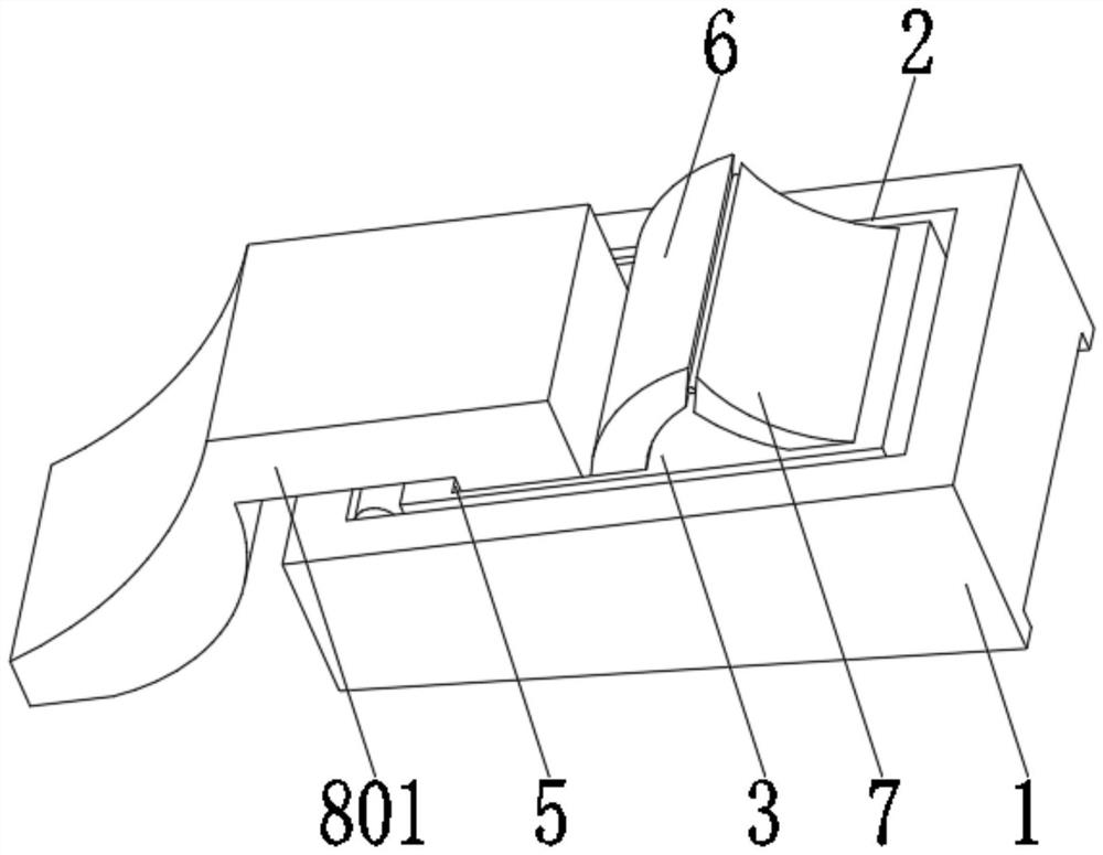
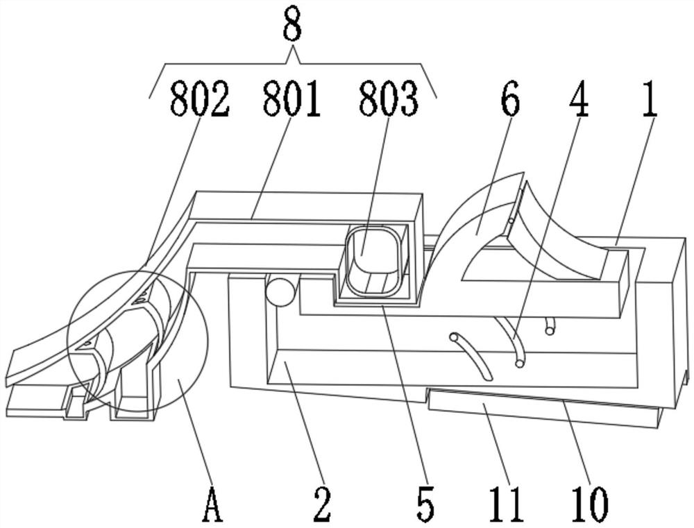
[0028] see Figure 1-4 , the present invention provides a technical solution: a hardware door suction, comprising a base 1, a telescopic groove 2 is opened on the top of the base 1, a swinging plate 3 is rotatably connected to one side of the telescopic groove 2, and the inner bottom of the telescopic groove 2 swings The spring 4 is fixedly connected with the swinging plate 3, the top of the swinging plate 3 is provided with a reset slot 5, the inner bottom of the reset slot 5 is slidably connected with an arc-shaped convex plate 6, and the arc-shaped convex plate 6 extends to one end outside the reset groove 5 for rotational connection There is an arc-shaped concave plate 7, one end of the arc-shaped concave plate 7 away from the arc-shaped convex plate 6 is rotatably connected with the swing plate 3, the bottom of the base 1 is inclined design, the bottom of the base 1 is provided with a positioning groove 10, and the interior of the positioning groove 10 A positioning devic...

Embodiment 2

[0032] see Figure 1-4 , the present invention provides a technical solution: on the basis of the first embodiment, a trigger dust collector 8 is installed inside the reset slot 5, the top of the trigger dust collector 8 extends to the outside of the reset slot 5, and the trigger dust collector 8 is triggered. A one-way control device 9 is installed inside.

[0033] The triggering vacuum device 8 includes a triggering frame 801, the triggering frame 801 is an elastic soft frame, and one end of the triggering frame 801 extending to the outside of the reset groove 5 is connected with a vacuuming frame 802, and a rubber airbag 803 is installed inside the triggering frame 801, and the rubber airbag 803 The interior is filled with air.

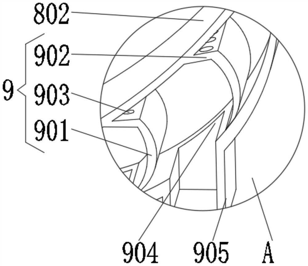
[0034] The one-way control device 9 includes an arc baffle 901 , the arc baffle 901 is evenly installed on the inner bottom of the vacuuming frame 802 , and the top of the arc baffle 901 is fixedly connected to the inner top of the vacuuming frame...

Embodiment 3

[0038] see Figure 1-5 , the present invention provides a technical solution: on the basis of the first embodiment, the anti-skid plate 112 includes a second mounting plate 1121, the top of the second mounting plate 1121 is evenly installed with a longitudinal plate 1122, and the bottom of the second mounting plate 1121 is evenly installed with a transverse plate 1123, the ends of the longitudinal plate 1122 and the transverse plate 1123 away from the second mounting plate 1121 are fixedly connected with anti-skid bumps 1124, and the outside of the anti-skid bumps 1124 is covered with anti-slip rubber sleeves 1125.

[0039] One side of the mounting plate 111 close to the anti-skid plate 112 is uniformly provided with longitudinal grooves 1126 that are adapted to the longitudinal plate 1122, and one side of the longitudinal groove 1126 is uniformly provided with transverse grooves 1127 that are adapted to the transverse plate 1123. The longitudinal plate 1122 Extending to the i...


PUM


Abstract

The invention discloses a hardware door stopper, which relates to the technical field of hardware and comprises a base. A telescopic slot is provided on the top of the base. One side of the telescopic slot is rotatably connected to a swing plate. The spring is fixedly connected with the oscillating plate, and the top of the oscillating plate is provided with a reset groove, and the inner bottom of the reset groove is slidably connected with an arc-shaped convex plate, and the end of the arc-shaped convex plate extending to the outside of the reset groove is rotatably connected with an arc An arc-shaped concave plate, the end of the arc-shaped concave plate away from the arc-shaped convex plate is rotatably connected with the swing plate. The hardware door stopper can facilitate the installation and use of the door stopper, reduce the installation cost of the door stopper, facilitate the popularization and use of the door stopper, increase the selectivity when replacing the door stopper, reduce the cost of door stopper replacement and maintenance, and reduce the cost of the door stopper. Collisions between the door stoppers increase the service life of the door stoppers, and at the same time have multiple functions, which can effectively buffer the force of the door stoppers when they collide.

Description

technical field [0001] The invention relates to the technical field of hardware, in particular to a hardware door suction. Background technique [0002] Door suction, also commonly known as door touch, is a device that holds and positions the door panel after the door leaf is opened to prevent the door from shaking and closing due to wind blowing or touching. The door suction is divided into permanent magnet door suction and electromagnetic door suction. Two types, permanent magnet door suction is generally used in ordinary doors and can only be controlled manually; electromagnetic door suction is used in electronically controlled door and window equipment such as fire doors, and has both manual control and automatic control functions. Electromagnetic door suction consumes electricity when in use. large, so it can only be used in some special places. [0003] Chinese invention CN107191080B discloses an invisible door suction, including a door suction main body and a braking...

Claims


Application Information

Patent Timeline
Patent Type & Authority Patents(China)
IPC IPC(8): E05C17/02B08B5/04
CPCE05C17/02B08B5/04
Inventor 李增非
Owner 博创金龙五金(温州)有限公司
Learn More