
Rotary wheel and rotary vane compressor

A compressor and runner technology, applied in the field of volumetric rotary rotor compressors, can solve the problems of increased leakage value, easy jamming, affecting the working efficiency and service life of the compressor, and achieves a small displacement angle and stable overall movement. , compact structure

Inactive Publication Date: 2021-04-06
南通金鼎天轮动力科技有限公司
View PDF1 Cites 0 Cited by
  • Summary
  • Abstract
  • Description
  • Claims
  • Application Information

AI Technical Summary

Problems solved by technology

The main structure of the rotary compressor is the rolling rotor compressor and the swinging rotor compressor, but there is contact friction between the moving parts, which leads to the increase of the leakage value after the contact wear of the parts, which directly affects the working efficiency of the compressor. and service life; Chinese application number 99114653.0 discloses a rolling rotor compressor with circular arc hinged isolation blades, and the hinged blades also have contact friction with the blade grooves, which are easy to get stuck

Method used


Image

  • Rotary wheel and rotary vane compressor
  • Rotary wheel and rotary vane compressor
  • Rotary wheel and rotary vane compressor

Examples


no. 1 example

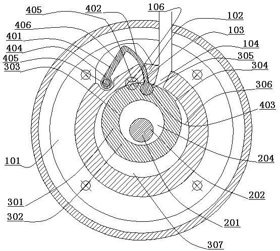
[0041] Such as figure 1 As shown, the rotary vane compressor includes a stator 101 , a crankshaft 201 , a rotary wheel 301 and a rotary vane 401 . On the wall surface of the cylinder liner 102 of the stator 101, a rotary vane groove 103 is arranged radially, and the two sides of the rotary vane groove 103 are provided with an air inlet 104 and an exhaust port 105, and an exhaust valve 106 is arranged on the exhaust port 105 . The shaft body 202 of the crankshaft 201 is arranged concentrically with the cylinder liner 102 , and the journal 204 of the crankshaft 201 is arranged inside the stator 101 . The wheel sleeve 303 at the center of the wheel body 302 of the runner 301 is arranged on the outside of the journal 204, and the outer circular wall surface 304 of the wheel body 302 is provided with a circular slide groove 305; the runner 301 separates the cylinder chamber 306 inside the stator 101 into a crescent Shaped volume cavity 307 . The top of the arc-shaped blade 402 o...


PUM


Abstract

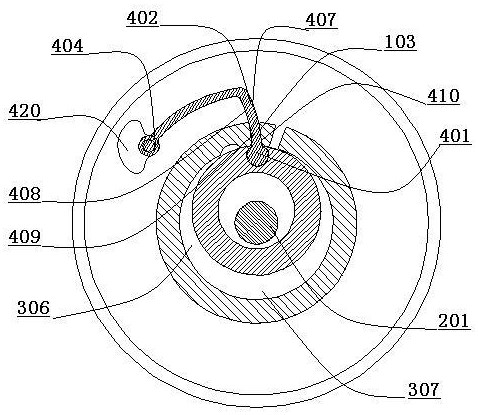
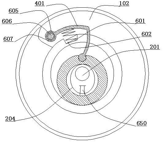
The invention discloses a rotary wheel and rotary vane compressor. The rotary wheel and rotary vane compressor comprises a stator, a crankshaft, a rotary wheel and a rotary vane, wherein a rotary vane groove is formed in the wall surface of a cylinder sleeve of the stator in the radial direction, and an air inlet and an air outlet are formed in two sides of the rotary vane groove; A wheel sleeve is arranged on a wheel body of the rotary wheel, a circular sliding groove is formed in the outer circle wall surface of the wheel body, and the rotating wheel divides an air cylinder chamber in the stator into a crescent volume cavity; a hinge column is arranged at the top of an arc-shaped vane of the rotary vane and is arranged in the circular sliding groove of the wheel body, a rotary shaft of the rotary vane is arranged in the rotary shaft seat of the stator, and the arc-shaped blade of the rotary vane is arranged in the rotary vane groove; and the rotary wheel translates in the air cylinder chamber and drives the rotary vane to swing, the arc-shaped vane of the rotary vane divides the crescent volume cavity, the element volume of the volume cavity changes, and air suction and exhaust work are performed. According to the technology, the rotary vane rotates and swings to control the rotary wheel to translate, moving parts are not in sliding contact, and various properties are greatly improved.

Description

technical field [0001] The invention relates to a volumetric rotary rotor compressor, which relates to the technical field of fluid machinery manufacturing such as fans, pumps and compressors. Background technique [0002] At present, the rotary compressor of the small volumetric rotary compressor in the market has the advantages of simple structure, small volume, no suction valve, etc., and is widely used in the field of refrigeration. The main structure of the rotary compressor is the rolling rotor compressor and the swinging rotor compressor, but there is contact friction between the moving parts, which leads to the increase of the leakage value after the contact wear of the parts, which directly affects the working efficiency of the compressor. and service life; Chinese application number 99114653.0 discloses a rolling rotor compressor with circular arc hinged isolation blades, and the hinged blades also have contact friction with the blade grooves, which are easy to get...

Claims


Application Information

Patent Timeline
Patent Type & Authority Applications(China)
IPC IPC(8): F04C2/44F04C2/46F04C15/00F04C15/06F04C18/44F04C18/46F04C29/00F04C29/12
CPCF04C2/44F04C2/46F04C15/00F04C15/064F04C18/44F04C18/46F04C29/00F04C29/124F04C2240/10F04C2240/20
Inventor 周觉明
Owner 南通金鼎天轮动力科技有限公司
Learn More