Heat exchange structure and method of ultralow-temperature electromagnetic valve

A technology of heat exchange structure and solenoid valve, applied in the direction of valve heating/cooling device, valve operation/release device, valve details, etc., can solve the problems of elongating the height of ultra-low temperature solenoid valve and restricting the application range, etc., and achieve improvement Effects of heat exchange efficiency, distance reduction, and increase in contact area

Active Publication Date: 2021-04-06
张家港富瑞阀门有限公司
View PDF5 Cites 0 Cited by
  • Summary
  • Abstract
  • Description
  • Claims
  • Application Information

AI Technical Summary

Problems solved by technology

[0004] One of the purposes of the present invention is to solve the problem that the ultra-low temperature electromagnetic valve in the prior art will elongate the height of the ultra-low temperature electromagnetic valve itself in order to protect the coil for air heat exchange, which limits the application range

Method used


Image

  • Heat exchange structure and method of ultralow-temperature electromagnetic valve
  • Heat exchange structure and method of ultralow-temperature electromagnetic valve
  • Heat exchange structure and method of ultralow-temperature electromagnetic valve

Examples


Embodiment 1

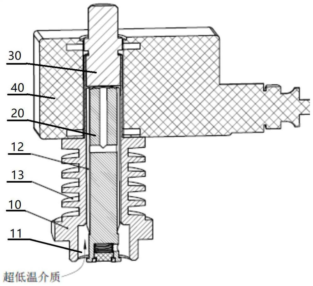
[0042] A heat exchange structure of an ultra-low temperature electromagnetic valve, wherein, such as figure 1 As shown, it includes: a valve seat 10 , a moving core 20 , a static core 30 , and a coil 40 .

[0043] Such as figure 1 As shown, the valve seat 10 has a movable cavity 11 and an annular structure 13 . The active chamber 11 is located in the valve seat 10 . The annular structures 13 are distributed on the outer surface of the valve seat 10, and the annular structures 13 are located on the side of the movable chamber 11. There are multiple annular structures 13, and there is a heat exchange space for air circulation between the multiple annular structures 13.

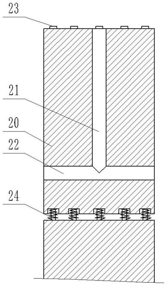
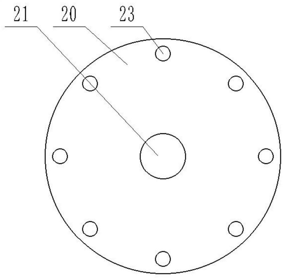
[0044] The moving core 20 is slidably arranged in the movable chamber 11 , and the moving core 20 and the side wall of the movable chamber 11 form a movement gap 12 , through which the heat exchange with the outside air is realized. The static core 30 is fixedly arranged on the movable cavity 11 , and the stati...

Embodiment 2

[0057] A heat exchange method for an ultra-low temperature electromagnetic valve, which includes the following steps:

[0058] When the ultra-low temperature medium gradually flows close to the coil 40 through the movement gap 12 around the moving core 20, during this process, when the medium contacts the side wall of the movable chamber 11, it continuously exchanges heat with the outside air to heat up the ultra-low temperature medium, so that the coil 40 The temperature of the medium at the place rises to the extent that the coil can bear;

[0059] At the same time, the valve seat 10 is processed with a multi-ring ring structure 13, so there is a heat exchange space between each ring structure 13, and when the outside air passes into the heat exchange space, it can communicate with each ring structure 13. Heat exchange greatly increases the contact area with the outside air, improves heat exchange efficiency, and achieves faster temperature rise. In this way, the distance re...


PUM


Abstract

The invention discloses a heat exchange structure of an ultralow-temperature electromagnetic valve, and relates to the technical field of ultralow-temperature gas storage devices. The heat exchange structure comprises a valve seat, a movable core, a fixed core and a coil. Firstly, a movement gap is formed between a movable cavity and the movable core, so that an ultralow-temperature medium flowing in the electromagnetic valve can continuously exchange heat with outside air through the movement gap, and heat is continuously taken away from the interior; and furthermore, the outer surface of the valve seat is arranged to be of a multi-circle annular structure, so that a plurality of heat exchange spaces are formed, the contact area with the outside air is greatly increased, the heat is taken away from the outside through cooperation with the interior, the heat exchange efficiency is improved, the distance required by medium heating can be shortened, and therefore the height requirement of the electromagnetic valve can be reduced. The problems that in the prior art, an ultralow-temperature electromagnetic valve is used for protecting the coil for air heat exchange, the height of the ultralow-temperature electromagnetic valve may be increased, and the application range is limited are solved.

Description

technical field [0001] The invention relates to the technical field of ultra-low temperature gas storage devices, in particular to a heat exchange structure of an ultra-low temperature electromagnetic valve. Background technique [0002] Solenoid valve (Electromagneticvalve) is an industrial equipment controlled by electromagnetic. It is an automatic basic component used to control fluid. It belongs to actuator and is not limited to hydraulic and pneumatic. It is used to adjust the direction, flow, speed and other aspects of media in industrial control systems. parameters. Solenoid valves can cooperate with different circuits to achieve the expected control, and the control accuracy and flexibility can be guaranteed. There are many kinds of solenoid valves. Different solenoid valves play a role in different positions of the control system. The most commonly used solenoid valves include check valves, safety valves, electromagnetic reversing valves, and speed regulating valve...

Claims


Application Information

Patent Timeline
Patent Type & Authority Applications(China)
IPC IPC(8): F16K31/06F16K49/00
CPCF16K31/0675F16K49/00Y02E60/14
Inventor 马君陆嘉君赵远
Owner 张家港富瑞阀门有限公司
Why Eureka
Try Eureka