LED display module detection device

A display module and detection equipment technology, applied in the direction of static indicators, instruments, etc., can solve the problem of difficulty in adapting to the needs of rapid mass production, the inability to judge the uniformity of LED light panels, the difference in brightness and chromaticity between LED light panels and LED light panels, artificial Low detection efficiency and other problems, to achieve the effect of shortening the height of the equipment, saving labor costs, and high accuracy

Inactive Publication Date: 2017-06-06
XIAN NOVASTAR TECH
View PDF6 Cites 9 Cited by
  • Summary
  • Abstract
  • Description
  • Claims
  • Application Information

AI Technical Summary

Problems solved by technology

For example, the human eye can only see whether there are dead lights or constant lights in a single LED light panel, but cannot judge the uniformity of the LED light panel or the difference in brightness and chromaticity between LED light panels.
On the other hand, manual detection is inefficient and difficult to adapt to the needs of rapid mass production

Method used


Image

  • LED display module detection device
  • LED display module detection device
  • LED display module detection device

Examples


no. 1 example

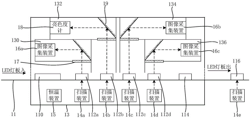
[0025] see figure 1 , The LED display module testing equipment proposed in the first embodiment of the present invention includes: a conveyor track system 11, a testing room 13, image testing chambers 130, 132, 134, 136, and scanning devices 14a-14e; and preferably also includes a constant temperature device 15.

[0026] Among them, the conveying track system 11 can transport and fix LED display modules such as LED lamp panels to designated locations, and its rails (such as conveyor belts) are equipped with automatic power-on and signal-on devices to ensure that the LED display modules arrive at designated locations and work normally. . It can be understood that, in addition to the track, the conveying track system 11 is typically also provided with a PLC (Programmable Logic Controller, programmable logic controller). Furthermore, from figure 1 It can be known that the transport track system 11 is configured with a pre-inspection waiting position 110 , image detection positi...

no. 2 example

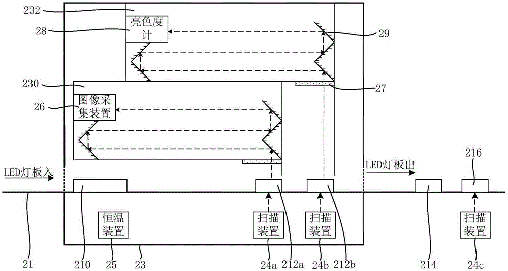
[0044] see figure 2 , The LED display module testing equipment proposed in the second embodiment of the present invention includes: a conveyor track system 21 , a testing room 23 , image testing chambers 230 , 232 , and scanning devices 24 a - 24 c ; and preferably also includes a constant temperature device 25 .

[0045] Among them, the conveying track system 21 can transport and fix LED display modules such as LED light boards to designated locations, and its rails (such as conveyor belts) are equipped with automatic power-on and signal-on devices to ensure that the LED display modules arrive at designated locations and work normally. . It can be understood that, in addition to the track, the conveying track system 21 is typically also provided with a PLC (Programmable Logic Controller, Programmable Logic Controller). Furthermore, from figure 2 It can be known that the transport track system 21 is configured with a pre-inspection waiting position 210 , image detection po...

no. 3 example

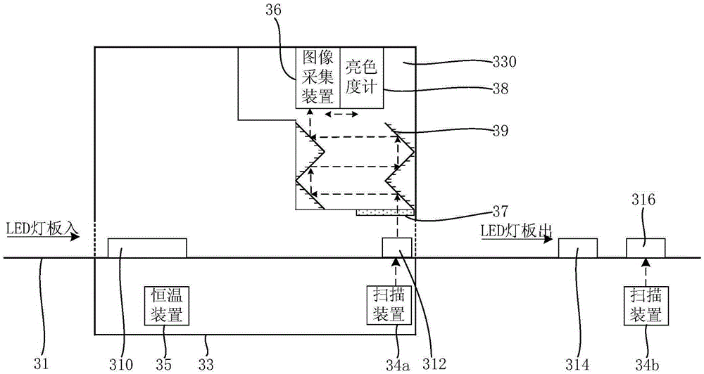
[0056] see image 3 , The LED display module inspection equipment proposed by the third embodiment of the present invention includes: a conveying track system 31 , an inspection chamber 33 , an image inspection chamber 330 , and scanning devices 34a, 34b; and preferably also includes a constant temperature device 25 .

[0057] Among them, the transmission track system 31 can transport and fix LED display modules such as LED lamp panels to designated positions, and its track (such as a conveyor belt) is equipped with automatic power-on and signal-on devices to ensure that the LED display modules arrive at designated positions and work normally. . It can be understood that, in addition to the track, the conveying track system 31 is typically also provided with a PLC (Programmable Logic Controller, programmable logic controller). Furthermore, from image 3 It can be known that the transport track system 31 is configured with a pre-inspection waiting position 310 , an image dete...


PUM


Abstract

The invention relates to an LED display module detection device, which comprises a conveying track system, a detection room, an image detection cavity and a scanning device, wherein the conveying track system is used for conveying an LED display module and comprises a before-detection waiting position, an image detection position, a post-detection waiting position and a correction factor writing position; the detection room is used for providing a dark room environment and the image detection position is located in the detection room; the image detection cavity is arranged in the detection room and comprises a light transmitting part, a reflecting mirror and a detecting device; and the scanning device is used for recognizing LED display modules conveyed to the image detection position and the correction factor writing position. Thus, qualification detection on the LED display module such as an LED lamp board can be automatically completed, the brightness or the chromaticity of the LED lamp board can be automatically corrected, and compared with the existing manual detection method, detection of the invention is high in accuracy, quantization is easy, the efficiency is greatly improved, and the manual cost is saved; and as the reflecting mirror is adopted, the height of the device can be shortened, and requirements on the height of a plant are further reduced.

Description

technical field [0001] The invention relates to the technical field of LED display, in particular to a detection device for an LED display module. Background technique [0002] LED display is a flat panel display device composed of LED dot matrix. With the rapid development of this industry, LED display is widely used in various occasions of daily life, with adjustable brightness range, safety and environmental protection, energy saving, color It has a series of advantages such as bright colors, large viewing range, and clear content. Compared with other traditional information media, its content is easy to update, low in cost, and good in timeliness. In the display and dissemination of media, it has advantages that other media cannot match. [0003] Before the LED display screen leaves the factory, the qualification of the LED light board needs to be tested, such as the detection of dead lights, long-on lights, and LED lights whose brightness and chromaticity do not meet t...

Claims


Application Information

Patent Timeline
Patent Type & Authority Applications(China)
IPC IPC(8): G09G3/00
Inventor 赵星梅王伙荣张光朋
Owner XIAN NOVASTAR TECH
Why Eureka
Try Eureka