Steel pipe assembly-welding device and rapid installation and movement method thereof

A technology of steel pipe groups and steel pipes, applied in auxiliary devices, welding equipment, tubular objects, etc., can solve the problems of low economic value of the project, small design section, inconvenient installation, etc., and achieve the goals of reducing preparation time, increasing added value, and optimizing design Effect

Active Publication Date: 2015-01-28
CHENGDU ALANGTECH
View PDF13 Cites 9 Cited by
  • Summary
  • Abstract
  • Description
  • Claims
  • Application Information

AI Technical Summary

Problems solved by technology

However, the existing technology has certain limitations. For example, whether it is a steel pipe trolley or a subsequently designed steel pipe welding device, there are problems of inconvenient installation and difficult movement, especially in underground projects where multiple steel pipes are operated at the same time. The design section of the transportation branch tunnel is small. If the welding device is installed multiple times in the tunnel, it will lead to long construction period and low economic value of the project.

Method used


Image

  • Steel pipe assembly-welding device and rapid installation and movement method thereof
  • Steel pipe assembly-welding device and rapid installation and movement method thereof
  • Steel pipe assembly-welding device and rapid installation and movement method thereof

Examples


Embodiment 1

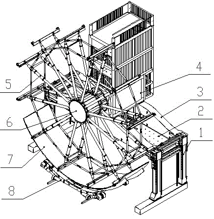
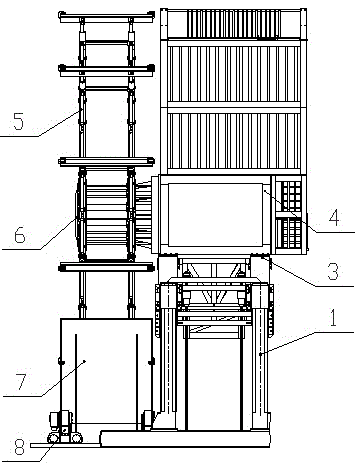
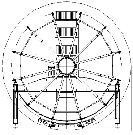
[0028] Such as Figure 1 to Figure 4 As shown, a steel pipe assembly welding device includes a column 1, a beam 2 and a main body 4, the two ends of the beam 2 are connected to the column 1, the main body shaft 6 is connected with a rotary support frame 5, and the main body 4. Set above the crossbeam 2, the connection between the crossbeam 2 and the column 1 has a positioning clamping and lifting device, and the bottom of the beam 2 or the column 1 is provided with a walking device 9; The structure can reduce the height of the whole device, greatly reduce the overall volume of the device, and facilitate transportation and transfer.

[0029] Such as Figure 1 to Figure 4 As shown, the lower part of the main body 4 is connected with a horizontal turning device, and the horizontal turning device is installed on the supporting plate 3 of the main body above the beam; the horizontal turning of the main body reduces the transport width of the entire assembly welding device.

[003...

Embodiment 2

[0039] In this embodiment, the steel pipe assembly and welding device is applied to on-site assembly and welding of large steel pipes in a certain tunnel.

[0040] Such as Figure 1 to Figure 4 As shown, a steel pipe assembly welding device includes a column 1, a beam 2 and a main body 4, the two ends of the beam 2 are connected to the column 1, the main body shaft 6 is connected with a rotary support frame 5, and the main body 4. Set above the crossbeam 2, the connection between the crossbeam 2 and the column 1 has a positioning clamping and lifting device, and the bottom of the beam 2 or the column 1 is provided with a walking device 9; The structure can reduce the height of the whole device, greatly reduce the overall volume of the device, and facilitate transportation and transfer.

[0041] Such as Figure 1 to Figure 4 As shown, the lower part of the main body 4 is connected with a horizontal turning device, and the horizontal turning device is installed on the supporting...

Embodiment 3

[0050] In this embodiment, the main difference from Embodiment 1 and Embodiment 2 is that the rotating device under the main body is changed to a translation device, and the traveling device adopts a track-type seam welding trolley.

[0051] Such as Figure 1 to Figure 4 As shown, a steel pipe assembly welding device includes a column 1, a beam 2 and a main body 4, the two ends of the beam 2 are connected to the column 1, the main body shaft 6 is connected with a rotary support frame 5, and the main body 4 is arranged above the beam 2, the lower part of the main body 4 is connected with a translation device, the connection between the beam 2 and the column 1 has positioning clamping and lifting settings, and the device is also equipped with a walking device 9.

[0052] In this embodiment, the moving direction of the translation device is perpendicular to the crossbeam, so that the main body can move towards the middle of the whole device, reducing the width of the entire assem...


PUM


Abstract

The invention discloses a steel pipe welding technology. A steel pipe assembly-welding device comprises an upright column, a cross beam and a main machine body, wherein two ends of the cross beam are connected with the upright column; a rotation shaft of the main machine body is connected with a turning support frame; the main machine body is arranged above the cross beam; a horizontal turning device is connected with the lower part of the main machine body; a positioning, clamping and lifting device is arranged on a joint part of the cross beam and the upright column; the steel pipe assembly-welding device is also provided with a traveling device. A novel mechanical structure and a system method are adopted so that the steel pipe assembly-welding device is suitable for various welding needs of different directions, unequal pipe diameters and similar structures, has rapid installation and movement functions and advantageously optimizes special pipe steel transportation roads and sites, the preparation time is reduced and the engineering investment is saved.

Description

technical field [0001] The invention relates to the technical field of steel pipe welding, in particular to a steel pipe assembly welding device and a fast installation and moving method thereof. Background technique [0002] In order to solve the technical problems of manufacturing and installing large-scale steel pipes under specific environmental conditions, Chinese patent 200510020396.7 proposes an automatic manufacturing process for large-scale steel pipes. At the same time, Chinese patents 200520035203.0 and 200610020101.0 propose corresponding mechanisms to realize the mechanization of steel pipe manufacturing and installation in a horizontal state. Its advantage is to improve the mechanization and welding automation level of large-scale steel pipe manufacturing, reduce the difficulty of steel pipe hoisting and transportation, and reduce production costs, especially suitable for large-scale steel pipe engineering applications in the horizontal state in tunnels, and can...

Claims


Application Information

Patent Timeline
Patent Type & Authority Applications(China)
IPC IPC(8): B23K37/02
CPCB23K31/02B23K37/0461B23K37/053B23K2101/06
Inventor 彭智祥杨宗立彭智辉石昌玉彭鹏
Owner CHENGDU ALANGTECH
Why Eureka
Try Eureka