Internal structure for landing bag shape control

a technology of attenuation system and internal structure, which is applied in the direction of shock absorber, fluid mattress, system for re-entry to earth, etc., can solve the problems of reducing the stroke efficiency, the attenuation system may not be able to maintain vehicle stability, and the pitching motion is substantially more prominent, so as to reduce the overall height of the bag, reduce the rollover of payload, and increase the landing stroke efficiency

Inactive Publication Date: 2008-04-17
AIRBORNE SYST NORTH AMERICA OF CA
View PDF15 Cites 10 Cited by
  • Summary
  • Abstract
  • Description
  • Claims
  • Application Information

AI Technical Summary

Benefits of technology

[0007]In order to increase landing stroke efficiency and reduce payload rollover in an impact attenuation bag, the present invention provides a landing bag with an internal structure that gives the bag a flatter resting shape as compared with such bag without an internal structure. The internal structure includes one or more height-reducing elements, such as fabric panels or ribs, internal cords in a parallel or criss-cross lacing pattern, or internal straps or webbing, or a combination of the foregoing. The height-reducing elements extend from the upper interior surface of the landing bag to the lower interior surface and, by drawing the upper and lower surfaces closer together, reduce the overall height of the bag as compared with the same bag in the absence of such elements. The flatter shape provides significant performance enhancement by increasing the initial ground contact area and lowering the effective center of gravity of the vehicle / airbag assembly. As a result, the moment arm is reduced such that the payload is less likely to roll over upon impact. In addition, pressure and associated impact-attenuating forces build quickly to provide a faster, more efficient landing stroke.

Problems solved by technology

Until the flattened shape is reached, the impact attenuating force is almost non-existent, dramatically reducing the stroke efficiency.
If the effective landing center of gravity is raised because of an increase in airbag height to accommodate stroke efficiency loss, however, the increased moment arm results in the pitching motion becoming substantially more pronounced such that the attenuation system may not be able to maintain vehicle stability.
This can result in vehicle / payload roll-over and potentially damaging ground contact.

Method used


Image

  • Internal structure for landing bag shape control
  • Internal structure for landing bag shape control
  • Internal structure for landing bag shape control

Examples


Embodiment Construction

[0035]In describing preferred embodiments of the invention illustrated in the drawings, specific terminology will be resorted to for the sake of clarity. However, the invention is not intended to be limited to the specific terms so selected, and it is to be understood that each specific term includes all technical equivalents which operate in a similar manner to accomplish a similar purpose.

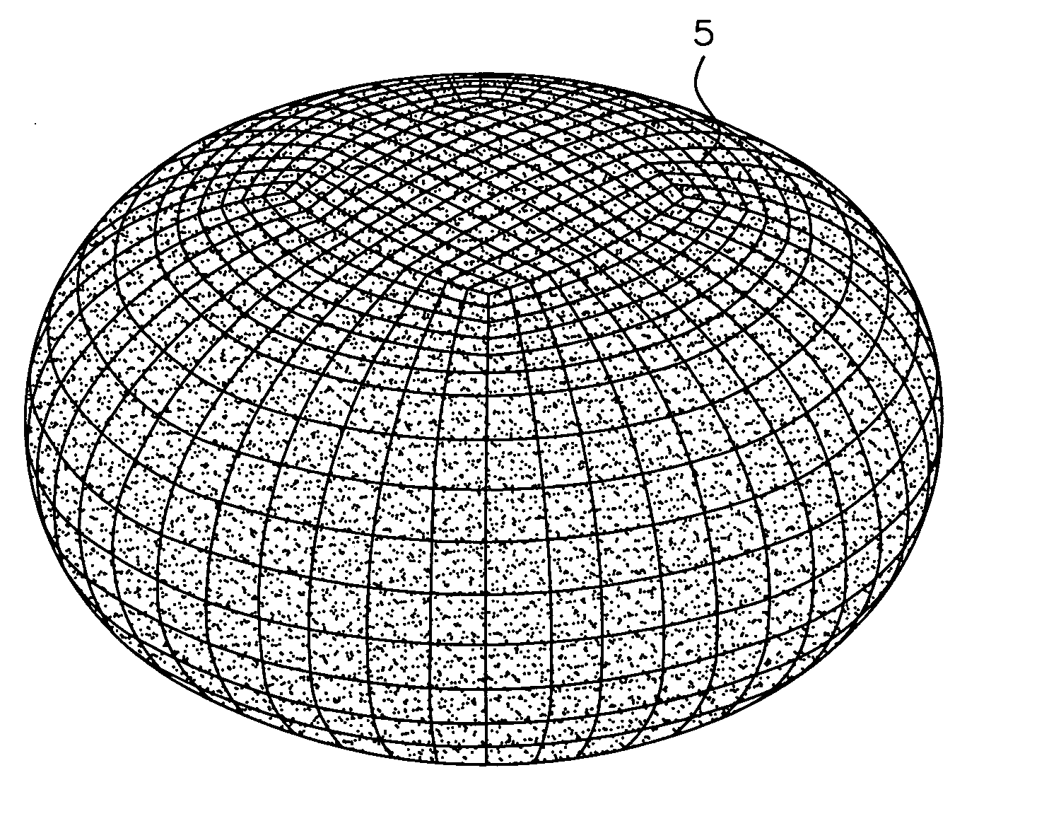
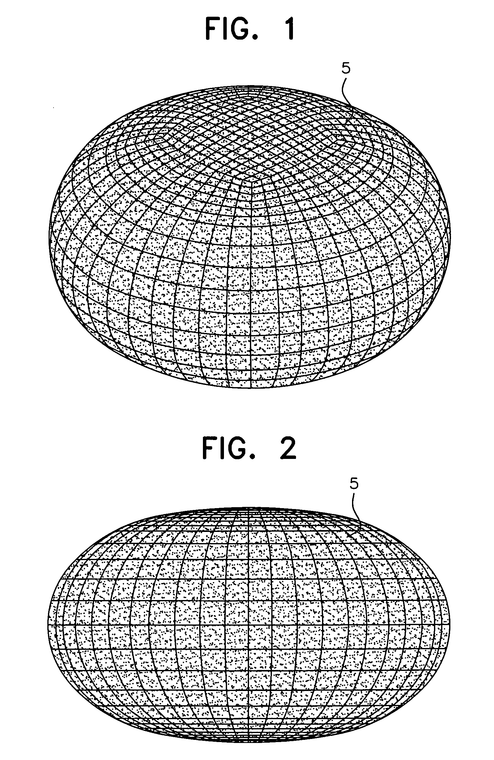
[0036]As representatively shown in FIGS. 1 and 2, conventional landing bags 5 adopt a naturally assumed inflated geometry when filled with a control volume of compressible gas, such as air or the like. This often results in a height and a footprint area prior to impact that are not ideal, particularly for landing scenarios with a horizontal velocity component, such as in a high wind environment. In such an environment, the moment produced by the product of the bag contact area, the bag internal pressure, the friction coefficient and the distance to the assembly center of gravity, or moment arm, a...


PUM


Abstract

An impact attenuation bag has a height-reducing structure in the form of an internal rib that draws the upper and lower surfaces of the bag closer together, reducing the overall height of the bag when inflated as compared with the same bag in the absence of the rib. This gives the bag a flatter resting shape that provides significant performance enhancement by increasing the initial ground contact area and lowering the vehicle assembly center of gravity. As a result, the moment arm is reduced making the payload less likely to roll over. The rib may be a fabric sheet or cord laced in a criss-cross or other lacing pattern that extends from the top of the bag to the bottom.

Description

BACKGROUND OF THE INVENTION[0001]1. Field of the Invention[0002]The present invention is related to the field of landing bag force attenuation and, more particularly, to an internal structure to control the shape of impact attenuation bags.[0003]2. Description of the Related Art[0004]Impact attenuation bags are well known to those skilled in the art. Such airbags are used to attenuate impact forces on the payload upon landing and include an airbag having a control volume of compressible gas. As used herein, the term “airbag” is not limited to bags containing air but includes impact attenuating bags that contain other gases or gas combinations.[0005]The shape of the control volume is determined by the naturally assumed inflated geometry of the airbag such that the bottom of the airbag tends to bulge. As a result, upon impact with the ground, the initial portion of the landing stroke is exhausted flattening the shape of the bag. During this time, the contact area between the ground an...

Claims


Application Information

Patent Timeline
Patent Type & Authority Applications(United States)
IPC IPC(8): F16F9/04
CPCB64D2201/00F16F9/04B64G1/62
Inventor TAYLOR, ANTHONY P.SINCLAIR, ROBERTSANDERS, JOHNSWEENEY, KEVIN
Owner AIRBORNE SYST NORTH AMERICA OF CA
Why Eureka
Try Eureka