Mounting rack for electromechanical equipment

A technology of electromechanical equipment and mounting frame, applied in mechanical equipment, machine/stand, lifting frame, etc., can solve the problems of user trouble, equipment damage, unfavorable safe and stable operation of electromechanical equipment, etc., to achieve enhanced stability and stable installation. Effect

Pending Publication Date: 2021-04-06
湖南宝烽设备股份有限公司
View PDF8 Cites 0 Cited by
  • Summary
  • Abstract
  • Description
  • Claims
  • Application Information

AI Technical Summary

Problems solved by technology

It is different from hardware, and refers to finished products that can achieve certain functions. Equipment is usually a general term for material materials such as machinery, devices, and facilities that people need in production and life. Electromechanical equipment refers to equipment that uses mechanical and electronic technologies. The commonly referred to as mechanical equipment is the most important part of electromechanical equipment. If some more sophisticated electromechanical equipment is installed directly on the ground during installation, it is easy to cause damage to the equipment, which is not conducive to the safe and stable operation of the electromechanical equipment.
[0003] However, the existing installation frame for electromechanical equipment cannot be adjusted according to the specifications and models of the electromechanical equipment, which has great limitations and brings troubles to users.

Method used


Image

  • Mounting rack for electromechanical equipment
  • Mounting rack for electromechanical equipment
  • Mounting rack for electromechanical equipment

Examples


Embodiment Construction

[0019] The following will clearly and completely describe the technical solutions in the embodiments of the present invention with reference to the accompanying drawings in the embodiments of the present invention. Obviously, the described embodiments are only some, not all, embodiments of the present invention. Based on the embodiments of the present invention, all other embodiments obtained by persons of ordinary skill in the art without making creative efforts belong to the protection scope of the present invention.

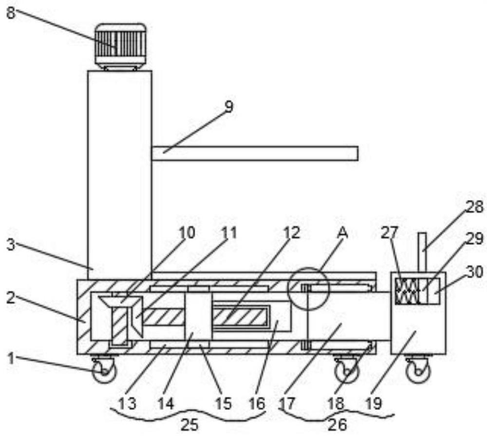
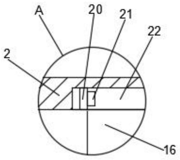
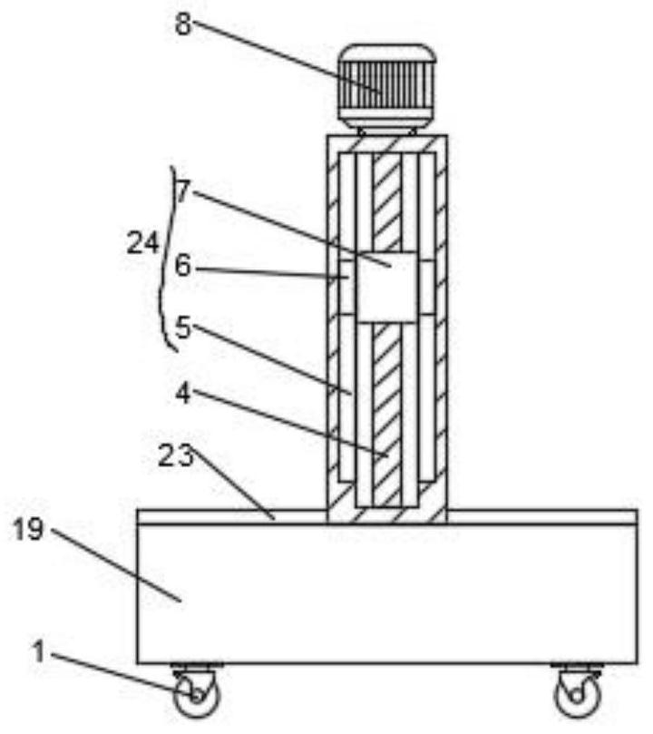
[0020] see Figure 1-4 , the present invention provides a technical solution: a mounting frame for electromechanical equipment, including a base 2 and a universal wheel 1, a placement plate 23 is fixedly connected to the top of the base 2, and a column 3 is fixedly connected to one side of the top of the base 2 , the top of the column 3 is fixedly connected with a three-phase asynchronous motor 8, the bottom of the three-phase asynchronous motor 8 is fixedly c...


PUM


Abstract

The invention discloses a mounting rack for electromechanical equipment. The mounting rack comprises a base and universal wheels, a placing plate is fixedly connected to the top end of the base, a stand column is fixedly connected to one side of the top end of the base, and a three-phase asynchronous motor is fixedly connected to the top end of the stand column; the bottom of the three-phase asynchronous motor is fixedly connected with a first screw rod, the first screw rod penetrates through the stand column and the base and is rotationally connected with a rotating shaft fixedly connected with the bottom end of one side in the base, the outer surface, located in the base, of the first screw rod is fixedly connected with a first bevel gear, and the first bevel gear is in engaged connection with a second bevel gear; and a second screw rod is fixedly connected to one side of the second bevel gear, a clamping plate is mounted at one side of the stand column, and a lifting assembly is mounted in the stand column. According to the mounting rack for the electromechanical equipment, the liftable clamping plate of the mounting rack is combined with a movable auxiliary supporting seat, so that the mounting rack can be suitable for electromechanical equipment of different sizes and specifications, due to the design of the movable auxiliary supporting seat, the placement stability of the electromechanical equipment can be enhanced, and the installation is more stable.

Description

technical field [0001] The invention relates to the technical field of electromechanical equipment, in particular to a mounting frame for electromechanical equipment. Background technique [0002] Electromechanical equipment generally refers to machinery, electrical appliances, and electrical automation equipment. In construction, it refers to the general term for machinery and pipeline equipment other than geotechnical, carpentry, steel bars, and muddy water. It is different from hardware, and refers to finished products that can achieve certain functions. Equipment is usually a general term for material materials such as machinery, devices, and facilities that people need in production and life. Electromechanical equipment refers to equipment that uses mechanical and electronic technologies. The commonly referred to as mechanical equipment is the most important part of electromechanical equipment. If some more sophisticated electromechanical equipment is installed directly...

Claims


Application Information

Patent Timeline
IPC IPC(8): F16M11/04F16M11/18F16M11/42B66F7/00B66F7/28
CPCF16M11/046F16M11/42
Inventor 林艳
Owner 湖南宝烽设备股份有限公司
Why Eureka
Try Eureka