
Saw blade quality detection equipment for building materials and buildings

A detection equipment and construction technology, which is applied in the field of saw blade quality detection equipment for building materials and construction, can solve the problems of difficult to see the saw blade intuitively and the effect is not obvious, and achieve the effect of easy detection

Inactive Publication Date: 2021-04-06
朱艳珍
View PDF0 Cites 2 Cited by
  • Summary
  • Abstract
  • Description
  • Claims
  • Application Information

AI Technical Summary

Problems solved by technology

[0004] In order to overcome the shortcomings of the existing method that the effect is not obvious, and it is difficult for the staff to visually see whether the saw blade is good or bad, the technical problem of the present invention is: to provide a rigid saw blade that is convenient for the staff to intuitively check the quality of the saw blade. Saw blade quality inspection equipment for building materials and construction to see whether the quality of the saw blade is good or bad

Method used


Image

  • Saw blade quality detection equipment for building materials and buildings
  • Saw blade quality detection equipment for building materials and buildings
  • Saw blade quality detection equipment for building materials and buildings

Examples


Embodiment 1

[0069] A kind of saw blade quality inspection equipment for building materials construction, such as figure 1 As shown, it includes a base 1, a mounting plate 2, a detection mechanism 3 and a placement mechanism 4. The top of the base 1 is provided with a mounting plate 2, the left side of the top of the mounting plate 2 is provided with a detection mechanism 3, and the right side of the top of the mounting plate 2 is provided with a placement mechanism. Institution 4.

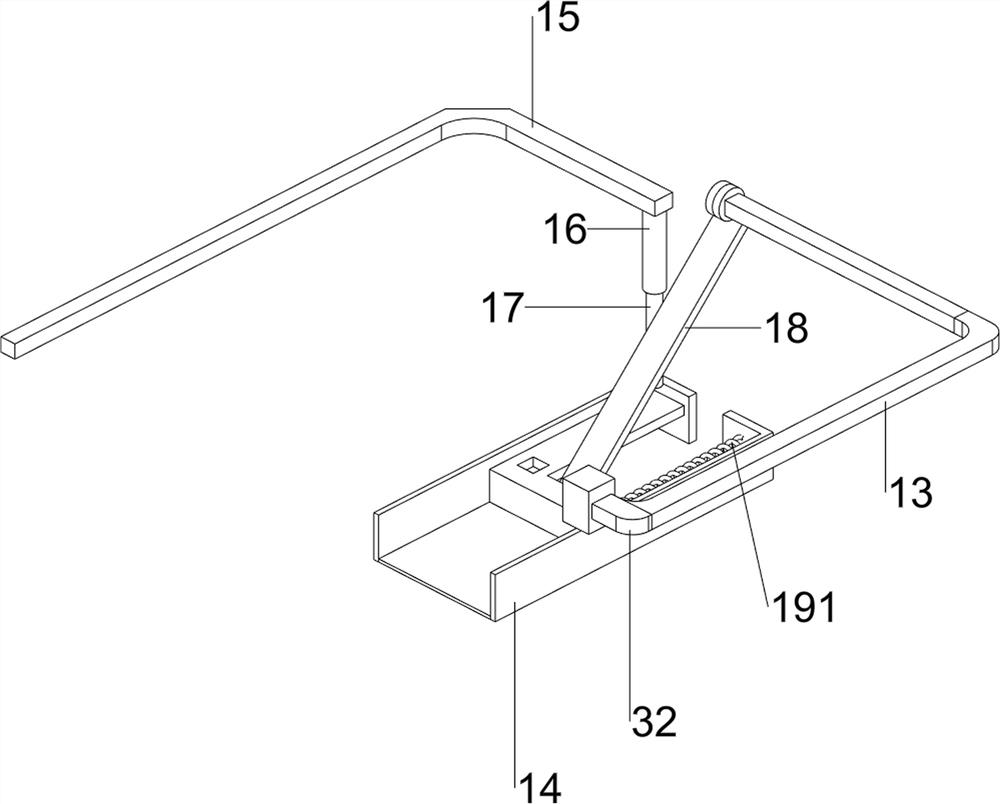
[0070] Such as figure 2As shown, the detection mechanism 3 includes an L-shaped rod 30, a cylinder 31, a connecting block 32 and a detection watermark device 33, the left front side of the top of the mounting plate 2 is provided with an L-shaped rod 30, the right end of the L-shaped rod 30 is provided with a cylinder 31, and the cylinder 31 The telescopic rod is connected with a connection block 32, and a detection watermark device 33 is provided at the bottom of the connection block 32.

[0071] Such as ...

Embodiment 2

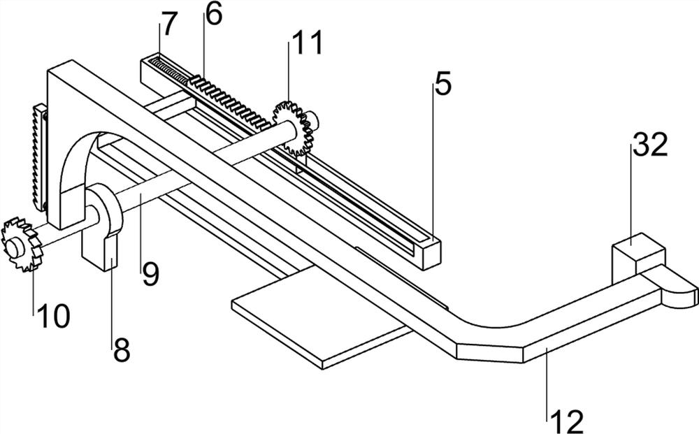
[0074] On the basis of Example 1, such as Figure 4 As shown, it also includes a first slide rail 5, a rack push plate 6, a first spring 7, a bearing seat 8, a second rotating shaft 9, a ratchet 10, a gear 11 and a special-shaped rod 12, and the left rear side of the top of the mounting plate 2 is provided There is a first slide rail 5, on which a rack push plate 6 slides, and a first spring 7 is connected between the left side of the rack push plate 6 and the inner wall of the first slide rail 5, and the top of the mounting plate 2 The left front side is provided with a bearing seat 8, the bearing seat 8 is provided with a second rotating shaft 9, the front side of the second rotating shaft 9 is provided with a ratchet 10, and the rear side of the second rotating shaft 9 is provided with a gear 11, and the gear 11 and the first rack push plate 6, the front right part of the connecting block 32 is provided with a special-shaped rod 12, and the ratchet bar of the special-shaped...


PUM


Abstract

The invention relates to detection equipment, in particular to saw blade quality detection equipment for building materials and buildings. According to the saw blade quality detection equipment for building materials and buildings, when quality detection work is conducted on a saw blade, a worker can conveniently and visually see whether the saw blade quality is good or not. Saw blade quality detection equipment for building materials and buildings comprises a base, and a mounting plate is arranged at the top of the base; a detection mechanism is arranged on one side of the top of the mounting plate; and a placing mechanism is arranged on the other side of the top of the mounting plate. Through the cooperation of the detection mechanism and the placing mechanism, a worker only needs to place a saw blade and paper to be detected and controls the air cylinder to work, and then the saw blade can be automatically detected; and the rack pushing plate is made to move rightwards intermittently, and therefore automatic feeding work of the saw web can be achieved.

Description

technical field [0001] The invention relates to a detection device, in particular to a quality detection device for saw blades used in building materials and construction. Background technique [0002] A saw blade is a general term for thin circular cutters used to cut solid materials. The saw blade is usually installed on a machine that can drive it to rotate like an electric drill. Because the output shaft of this type of machine is usually cylindrical, the opening on the saw blade There are holes for installation on this type of machine, so it is necessary to carry out quality inspection on the saw blade to see if the hole is qualified. At present, the inspection work on the saw blade is carried out manually, and the circular inspection device is used manually on the saw blade. Inspection work, but the effect of this method is not obvious, and it is difficult for the staff to intuitively see whether the saw blade is good or bad. [0003] Therefore need to design a kind o...

Claims


Application Information

Patent Timeline
Patent Type & Authority Applications(China)
IPC IPC(8): G01N19/08G01N21/88G01B5/20G01B11/24
CPCG01B5/20G01B11/24G01N19/08G01N21/8803
Inventor 朱艳珍
Owner 朱艳珍
Learn More