Table with automatic tabletop cleaning function

A self-cleaning, table technology, applied in the table field, can solve laborious and troublesome problems

Active Publication Date: 2021-04-09
广东名美轩家具实业有限公司
View PDF6 Cites 0 Cited by
  • Summary
  • Abstract
  • Description
  • Claims
  • Application Information

AI Technical Summary

Problems solved by technology

[0004] In order to overcome the shortcomings that people need to hold a rag to clean the desktop, they need to move their hands constantly, and after a long time, it is more laborious, and after cleaning the desktop, they also need to clean their hands, which is more troublesome. The technical problem is: provide a A table that can replace people to clean the desktop, is convenient and quick, and people can control the size of the cleaning force, which is relatively labor-saving and highly efficient.

Method used


Image

  • Table with automatic tabletop cleaning function
  • Table with automatic tabletop cleaning function
  • Table with automatic tabletop cleaning function

Examples


Embodiment 1

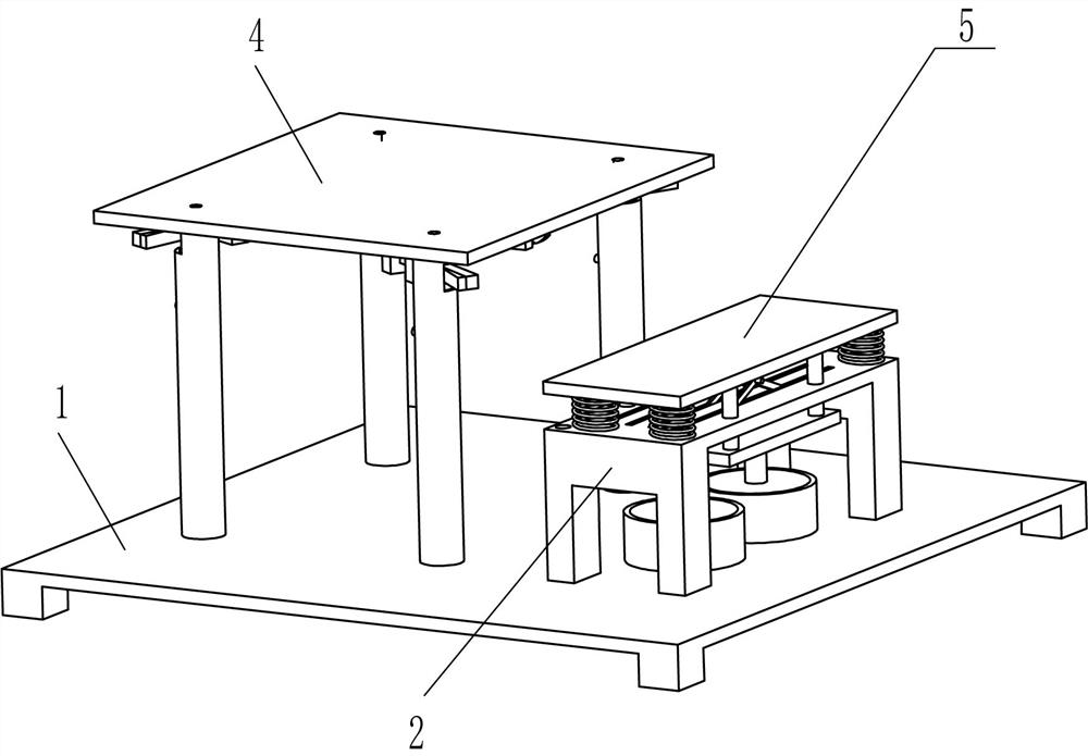
[0025]An automatic cleaning desktop, such asfigure 1 ,figure 2 ,image 3 withFigure 5 As shown, there is a base 1, a support frame 2, an air compression mechanism 3, a hole tablet 4, and a hydraulic mechanism 5, and a support frame 2 in the top of the base 1, and air compression is provided on the top of the base 1. Mechanism 3, the top of the air compression mechanism 3 is provided with a hole tablet 4, and the front side of the base 1 is provided with a hydraulic mechanism 5, and the hydraulic mechanism 5 is coupled to the air compression mechanism 3.

[0026]The air compression mechanism 3 includes a first cylinder 31, a first bump 32, a sliding hollow rod 33, a second cylinder 34, a hose 35, a floating block 36, a sliding block 37, and a one-way valve 38, and the base 1 The rear side interval has four first cylindrical 31, and the bottom portion of the first cylinder 31 is connected to the hydraulic mechanism 5, and there is a hole tablet 4, and the first circle is fixed between the...

Embodiment 2

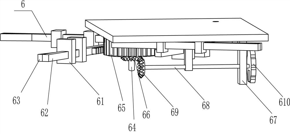
[0032]On the basis of Example 1, such asfigure 1 ,Figure 4 withFigure 7As shown, there is a linkage mechanism 6, and the linkage mechanism 6 includes a second fixing block 61, a rack 62, a second bump 63, a first driving rod 64, a column gear 65, a first cone gear 66, a third fixation. Block 67, the second drive rod 68, the second tapered gear 69, and the recess 610, the bottom intermediate rotation of the hole tablet 4 has a first driving rod 64, and the upper circumferential direction of the first drive rod 64 is fixed to the column gear 65. , There is eight second fixing blocks 61, and each of the two second fixed blocks 61 is a set, and the two second fixed blocks 61 of each group are slidable. The rack 62, the outer side surface of the four racks 62 is fixed to the second bump 63, the second bump 63 side is slidable with the hose 35, and the rack 62 meshes with the column gear 65, the first drive rod 64 lower circumference The first bevel gear 66 is fixed to the top right side ...

Embodiment 3

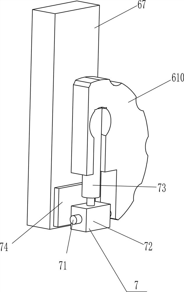
[0035]On the basis of Example 1 and Example 2, iffigure 1 withFigure 6 As shown, it is also included, and the tensioning device 7 includes a second hinge 71, a rectangular block 72, a radial rod 73, and a rubber block 74, and a lower portion of the right third fixing block 67 is fixed. Block 74, the lower partial embedded hinged article hingedly coupled with the second hinge rod 71, and the second hinge 71 has a rectangular block 72, and the rectangular block 72 is in contact with the rubber block 74, and the top of the rectangular block 72 is fixed. The rod 73, the rod 73 is embedded in the recess 610.

[0036]When people regulate the cleaning desktop strength, first, people pull the rod 73 to swing downward, the rod 73 swing down the rectangle block 72 forward, the rectangular block 72 is forward to the rubber block 74, at this time, the round rod 73 is The recess 610 is perpendicular, and then pulled the rod 73 to rotate the recess 610, the cleaning force can be adjusted, and when t...


PUM


Abstract

The invention relates to a table, in particular to a table with an automatic tabletop cleaning function. The technical problem is how to design a table with an automatic tabletop cleaning function, which can replace people to clean the tabletop conveniently and fast, can control the cleaning force by people, is more labor-saving and has high working efficiency. A table with an automatic tabletop cleaning function comprises a base of which one side is fixedly connected with a supporting frame; a hydraulic mechanism which is mounted on the base and used for providing power; and an air compression mechanism which is mounted on one side of the base, is connected and matched with the hydraulic mechanism and is used for cleaning the tabletop. People sit on the hydraulic mechanism, the hydraulic mechanism starts to operate under the action of gravity of people, the hydraulic mechanism operates to drive the air compression mechanism to operate, the air compression mechanism operates to clean a table board with holes, and people can have dinner on the table board with the holes Thus, the tabletop can be continuously cleaned, and the operation is convenient.

Description

Technical field[0001]The present invention relates to a table, in particular to a table that automatically cleans the desktop.Background technique[0002]People need to clean the desktop before dining, and now, most are people manually cleans the desktop. People need to have a rag to clean the desktop. Due to the constant mobile hand, time is long, comparison Fully, and after cleaning the desktop, you need to clean, more troublesome.[0003]Therefore, it is necessary to design an automatic cleaning desktop that can be cleaned to the desktop, convenient and fast, and people can control the size of the desktop, and more labor-saving.Inventive content[0004]In order to overcome people need to clean the grip to clean the desktop, you need to keep your mobile hand, the time is long, more laborious, and people need to clean the desktop, but also need to clean, more troublesome, technical issues: Provide one It can replace people to clean the desktop, convenient and fast, and people can control...

Claims


Application Information

Patent Timeline
Patent Type & Authority Applications(China)
IPC IPC(8): A47B31/00A47B83/02A47L11/00A47L11/40
CPCA47B31/001A47B83/024A47L11/00A47L11/4069Y02B40/00
Inventor 邹松
Owner 广东名美轩家具实业有限公司
Why Eureka
Try Eureka