
Perforating device for injection mold machining

A punching device and injection mold technology, applied in metal processing equipment, manufacturing tools, boring/drilling, etc., can solve problems such as low work efficiency, time-consuming and labor-intensive use, and inflexible use of drilling tools

Inactive Publication Date: 2021-04-09
余华
View PDF0 Cites 0 Cited by
  • Summary
  • Abstract
  • Description
  • Claims
  • Application Information

AI Technical Summary

Problems solved by technology

[0003] The traditional plastic injection mold drilling tooling is extremely inflexible. When drilling, the feed of the injection mold needs to cooperate with the up and down movement of the drill bit, which easily leads to manual control of the drilling position, and its work efficiency is low. Time-consuming

Method used


Image

  • Perforating device for injection mold machining
  • Perforating device for injection mold machining
  • Perforating device for injection mold machining

Examples


Embodiment 1

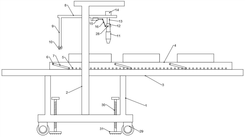
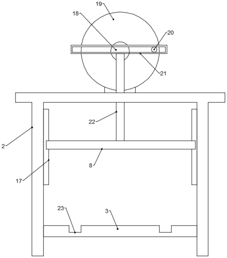
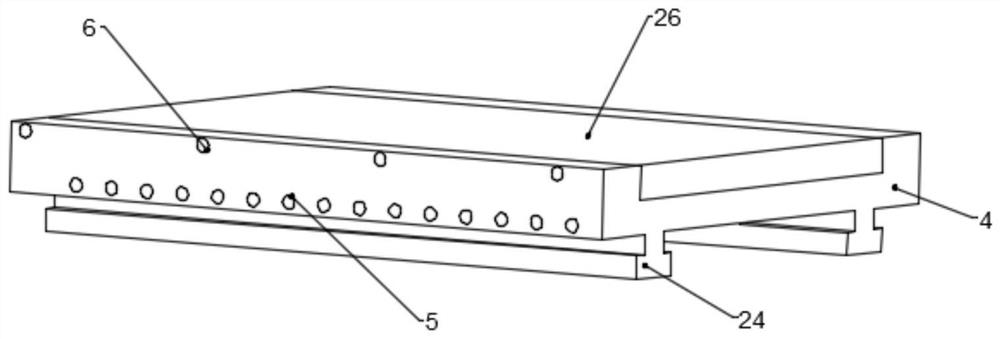
[0023] see Figure 1~4 , in an embodiment of the present invention, a punching device for injection mold processing includes a lower support frame 1 and an upper frame 2, the top end of the lower support frame 1 is provided with a drilling platform 3, and the drilling platform 3 is provided with a The sliding platform 4 is installed on it, and the side wall of the sliding platform 4 is provided with a row of upper connection holes 6 and a row of lower connection holes 5. The center position of the upper connection hole 6 is higher than the center position of the lower connection hole 5. The side of the installation slide table 4 is also provided with a plurality of push guide bars 7 and each end of each push guide bar 7 is provided with plugs inserted into the upper connection hole 6 and the lower connection hole 5 respectively. Column 25, the upper frame 2 is provided with a driving cross frame 8 located above the sliding table 4, the driving cross frame 8 is equipped with a ...

Embodiment 2

[0031] see figure 1The difference between this embodiment of the present invention and Embodiment 1 is that: the bottom of the lower support frame 1 is also provided with a universal moving wheel 29 and an adjustment screw 30, and the adjustment screw 30 spirally runs through the bottom of the lower support frame 1 and the bottom of the adjustment screw 30 A base plate 31 is provided, and the bottom surface of the base plate 31 is provided with a rubber protrusion. The setting of the universal moving wheel 29 facilitates the movement of the whole device, and the rotation adjustment screw 30 is used to adjust the height of the base plate 31. When the base plate 31 touches the ground and generates pressure with the ground The device is guaranteed.


PUM


Abstract

The invention discloses a perforating device for injection mold machining. The perforating device comprises a lower supporting frame and an upper frame, wherein a drilling platform is arranged at the top end of the lower supporting frame, a mounting sliding table sliding on the drilling platform is arranged on the drilling platform, and a row of upper connecting holes and a row of lower connecting holes are formed in the side wall of the mounting sliding table; a plurality of pushing guide rod strips are further arranged at the side portion of the mounting sliding table, a driving transverse frame located above the mounting sliding table is arranged on the upper frame, a rotating rod shaft is installed on the driving transverse frame, a drill bit is arranged at the bottom end of the rotating rod shaft, and the two end sides of the driving transverse frame are connected with upper frame supporting columns in an up-down sliding manner through connecting guide rails; and a feeding mechanism is arranged at the top of the upper frame, and a pushing guide rod right opposite to the pushing guide rod strips is further arranged at the end, away from the drill bit, of the driving transverse frame. The perforating device is simple in structure, an injection mold is automatically pushed to move in the drill bit feeding process, the drilling distances are equal, drilling positioning is accurate, automatic perforating is achieved, and the efficiency is high.

Description

technical field [0001] The invention relates to the technical field of injection mold processing, in particular to a punching device for injection mold processing. Background technique [0002] Injection molding is a tool for producing plastic products; it is also a tool for giving plastic products a complete structure and precise dimensions. Injection molding is a processing method used in mass production of certain complex-shaped parts; The injection molding machine injects into the mold cavity under high pressure, and after cooling and solidifying, the molded product is obtained. Drilling devices play a pivotal role in people's lives. Because of their fast drilling function, they are used in various automated factories for processing. [0003] The traditional plastic injection mold drilling tooling is extremely inflexible. When drilling, the feed of the injection mold needs to cooperate with the up and down movement of the drill bit, which easily leads to manual control ...

Claims


Application Information

Patent Timeline
IPC IPC(8): B23B41/00
CPCB23B41/00
Inventor 余华
Owner 余华
Learn More