
A belt conveyor tensioning system

A belt conveyor and tensioning system technology, applied in the direction of conveyors, conveyor objects, conveyor control devices, etc., can solve the problems of easy shock, motor suction, and inability to use winches in emergency, and achieves the possibility of lifting. The effect of controllability and improving stability

Active Publication Date: 2021-08-24
CHINA UNIV OF MINING & TECH
View PDF15 Cites 0 Cited by
  • Summary
  • Abstract
  • Description
  • Claims
  • Application Information

AI Technical Summary

Problems solved by technology

[0017] 1. When tensioning, the winch motor moves while the tensioning cylinder also moves. Since the speed is affected by the load, and the loads of the motor and the cylinder are different, it is difficult to control the running speed of the motor and the cylinder, and it is difficult to accurately control the movement position of the cylinder;
[0018] 2. After the tension force is reduced, the winch is used for tensioning. Due to the viscoelastic characteristics of the conveyor belt, the winch will be turned on and off when the tension is fine-tuned, and the brake needs to be turned on the motor first when the winch moves. When it moves again, it is difficult to match the opening of the brake with the action of the motor, and it is prone to impact;
[0019] 3. Use the motor to fine-tune the tension, the micro-movement of the motor is not easy to control, and the phenomenon of motor suction may occur; when there is a problem with the oil pump or the motor, the winch cannot be used for emergency use

Method used


Image

  • A belt conveyor tensioning system
  • A belt conveyor tensioning system

Examples


Embodiment Construction

[0045] The following is a specific embodiment of the present invention, and the present invention will be further described in conjunction with the accompanying drawings.

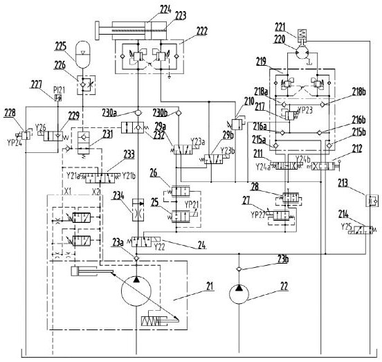
[0046] combine figure 1 As shown, a belt conveyor tensioning system, the oil outlet of the constant pressure pump 21 is connected to the first one-way valve I23a, and the oil outlet of the emergency pump 22 is connected to the second one-way valve I23b. The first one-way valve I23a and the second one-way valve I23b are respectively connected to the two-position three-way valve I24, the mechanical three-position four-way valve 212 and the two-position three-way valve III214 after confluence.

[0047] The two-position three-way valve I24 is connected to the speed control valve 234, the two-position two-way proportional valve I25 and the two-position two-way proportional valve II27;

[0048] The speed regulating valve 234 is connected to the hydraulically controlled two-position two-way valve II232, and the ...


PUM


Abstract

The invention discloses a belt conveyor tensioning system, which belongs to the technical field of belt conveyors. The constant pressure pump and the emergency pump are connected to the two-position three-way valve I, the mechanical three-position four-way valve and the two-position three-way valve III after being isolated by the one-way valve; Two-way proportional valve I and two-position two-way proportional valve II; the speed regulating valve is connected with a hydraulically controlled two-position two-way valve II, and the hydraulically controlled two-position two-way valve II is connected to the first oil inlet of the double balance valve II; The two-position two-way proportional valve I is connected to a pressure compensator I, and the pressure compensator I is respectively connected to a first two-position three-way valve II and a second two-position three-way valve II. The present invention adopts the form of proportional valve + pressure compensator to improve the controllability of the combined action of the winch system and the tensioning oil cylinder; real-time control of the overflow pressure of the electric proportional overflow valve to reduce the impact of the winch system in real time, and the lifting system is stable Reliability; real-time oil replenishment for the system through back pressure to prevent a cavity of the winch motor from being sucked empty under the action of load.

Description

technical field [0001] The invention relates to the technical field of belt conveyors, in particular to a belt conveyor tensioning system. Background technique [0002] Long-distance belt conveyors have the advantages of high degree of automation, low environmental pollution, and low transportation costs, and are widely used in many fields such as coal mining. Since the conveyor belt is a viscoelastic body, most of the energy stored or released by the belt during the start and stop of the conveyor forms a large stress fluctuation in the belt, and these stress fluctuations will cause the tension and deflection of the conveyor belt to occur. Variety. During use, when the tension decreases to a certain value, it will cause the conveyor belt to slip and fail to work normally. In addition, the elastic deformation and plastic deformation of the tape will cause the tape to become loose, causing serious accidents such as material spillage, coal accumulation, tape damage, etc., and...

Claims


Application Information

Patent Timeline
Patent Type & Authority Patents(China)
IPC IPC(8): B65G23/44B65G43/00
CPCB65G23/44B65G43/00
Inventor 杨春雨臧其亮卜令超陈斌代伟周林娜王国庆马磊
Owner CHINA UNIV OF MINING & TECH
Learn More