Single-shaft deep mixing pile drilling tool with inner-layer and outer-layer mixing teeth

An inner and outer double layer, stirring tooth technology, applied in sheet pile wall, construction, infrastructure engineering, etc., can solve the problems of single shaft deep stirring pile body quality defect, large disturbance of adjacent stratum, etc., to improve cutting and crushing efficiency, stratum The effect of small disturbance and improved efficiency

Pending Publication Date: 2021-04-09
王琪
View PDF0 Cites 1 Cited by
  • Summary
  • Abstract
  • Description
  • Claims
  • Application Information

AI Technical Summary

Problems solved by technology

[0007] The technical problem to be solved by the present invention is to provide a new type of single-axis deep-stirring pile, which overcomes the problems of the quality defect of the existing single-axis deep-stir

Method used


Image

  • Single-shaft deep mixing pile drilling tool with inner-layer and outer-layer mixing teeth
  • Single-shaft deep mixing pile drilling tool with inner-layer and outer-layer mixing teeth
  • Single-shaft deep mixing pile drilling tool with inner-layer and outer-layer mixing teeth

Examples


Example Embodiment

[0034] Example 1. The construction method of deep stirring pile to isolate the stratum outside the borehole to reduce disturbance

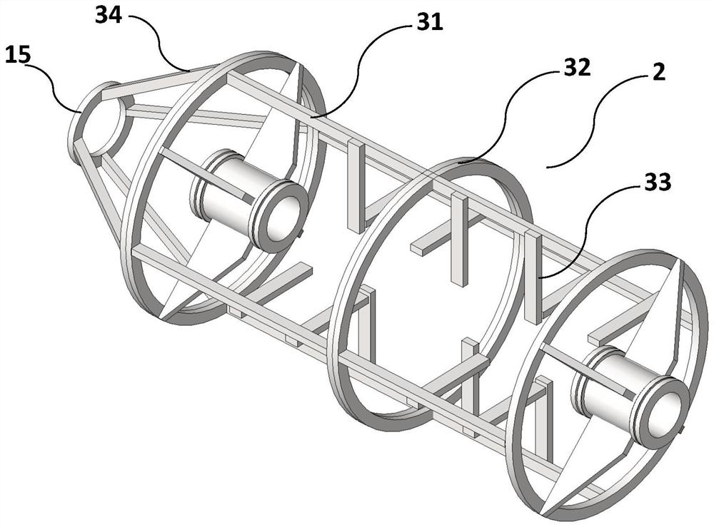
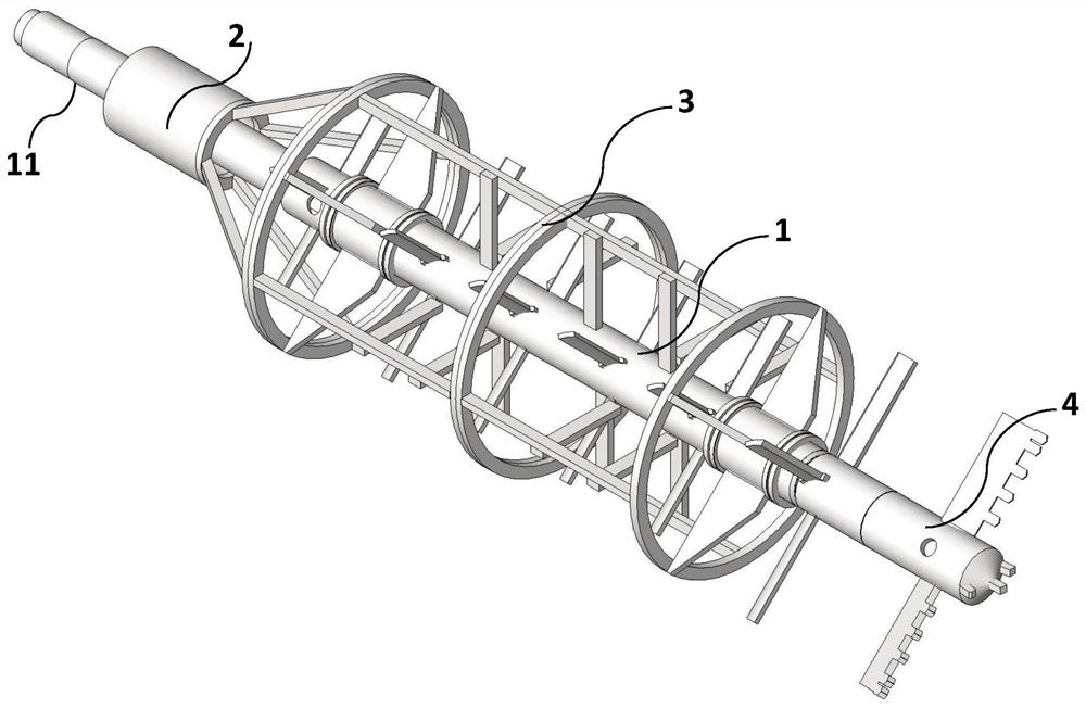
[0035] When the stirring teeth of the traditional stirring piles cut and break the stratum, there is still a large disturbance to the ground outside the borehole, thus affecting the construction facilities near the stirring piles. With the single-shaft stirring pile drilling tool of the present invention, the outer stirring cover 3 can isolate the broken soil in the borehole from the stratum outside the borehole, and when the inner stirring shaft 1 rotates with the drill pipe, it is distributed in the mixing The stirring teeth 12 on the shaft 1 are rotated inside the stirring hood 3, so that the disturbance to the formation outside the borehole caused by cutting and breaking the rock and soil blocks is greatly reduced.

Example Embodiment

[0036] Example 2. Construction method of deep stirring pile with bottom shotcrete to reduce drilling resistance and top shotcrete to be fully mixed

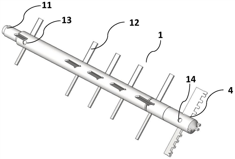
[0037] A drill bit 4 is connected to the lower end of the stirring shaft 1, and a bottom jetting port 14 is arranged at the lower part. When the downhole is drilled, the bottom jetting port 14 sprays slurry to lubricate the drill bit in time and reduce the resistance of the drilling process. At the same time, the inner stirring teeth 12 and the outer stirring teeth 33 encountered by the jetted slurry during the drilling process are mixed, so that the soil solidifying agent (slurry) and the broken rock and soil particles are mixed together.

[0038] When the drill pipe is lifted up, the top spraying port 13 starts to spray the slurry. The inner stirring teeth 12 and the outer stirring teeth 33 encountered by the sprayed slurry during the drilling process are mixed to make the soil solidifying agent (slurry) and crushing. Mixing th...


PUM


Abstract

The invention discloses a single-shaft deep mixing pile drilling tool with inner-layer and outer-layer mixing teeth. A drill rod of the single-shaft deep mixing pile drilling tool is of a double-layer structure, a mixing shaft and a drill bit are arranged at the lower end of the inner-layer drill rod, and the outer-layer drill rod is connected with a mixing cover; the outer-layer mixing teeth are arranged on the cylindrical hollowed-out mixing cover, and the inner-layer mixing teeth are arranged on the hollow mixing shaft; the inner-layer and outer-layer mixing teeth are arranged in a staggered mode in space and engaged with each other; the mixing cover covers the inner-layer mixing shaft; and a top slurry spraying opening is formed in the upper portion of the mixing shaft, and a bottom slurry spraying opening is formed in the drill bit. Rock-soil particles are efficiently broken and fully mixed with soil hardening agent slurry to form fluid hardened soil. The single-shaft deep mixing pile drilling tool has the social benefits of being environmentally friendly, safe and reliable, meanwhile, the manufacturing cost can be reduced, the construction period can be shortened, and great economic value is achieved.

Description

technical field [0001] The invention relates to the technical field of civil engineering, in particular to a single-axis deep-stirring pile drilling tool used for foundation reinforcement, rigid composite piles and water-stop curtain construction. Background technique [0002] In construction engineering, uniaxial deep-stirred piles are widely used as the main soft soil foundation reinforcement treatment and the peripheral piles of stiff composite piles. However, when the uniaxial deep stirring pile cuts and mixes the formation soil through the mixing blades, the soil between the mixing blades, especially the cohesive soil, is often tightly bonded to the blades and wraps around the mixing blades so that it cannot be cut and broken, making it It is difficult to mix with the soil curing agent slurry (such as cement slurry), which leads to major problems in the uniformity and quality of the deep stirring pile body. [0003] For areas highly sensitive to the surrounding environ...

Claims


Application Information

Patent Timeline
IPC IPC(8): E02D5/46
CPCE02D5/46
Inventor 不公告发明人
Owner 王琪
Why Eureka
Try Eureka