Turbine shell laryngeal structure

A turbine shell and mouthpiece technology, applied to engine components, machines/engines, internal combustion piston engines, etc., can solve the problems of turbocharger speed increase, turbine efficiency reduction, turbine flow capacity reduction, etc.

Pending Publication Date: 2021-04-09
康跃科技(山东)有限公司
View PDF0 Cites 0 Cited by
  • Summary
  • Abstract
  • Description
  • Claims
  • Application Information

AI Technical Summary

Problems solved by technology

[0014] Aiming at the deficiencies in the prior art, the present invention solves the problem of the uneven distribution of static pressure on the annulus surface of the turbine rotor inlet near the throat of the turbine shell in the traditional technology, which causes the turbine blades to experience large pressure changes when they pass through the throat during the rotation process. , so as to generate a large excitation effect on the turbine vibration, causing periodic vibration of the turbine blades and generating BPF noise at the vortex tip; the two airflows are sharply mixed near the throat, which obviously reduces the efficiency of the turbine; and due to the reduction of the flow capacity of the turbine, resulting The problem that the speed of the supercharger is obviously increased when the engine speed is low

Method used


Image

  • Turbine shell laryngeal structure
  • Turbine shell laryngeal structure
  • Turbine shell laryngeal structure

Examples


Embodiment 1

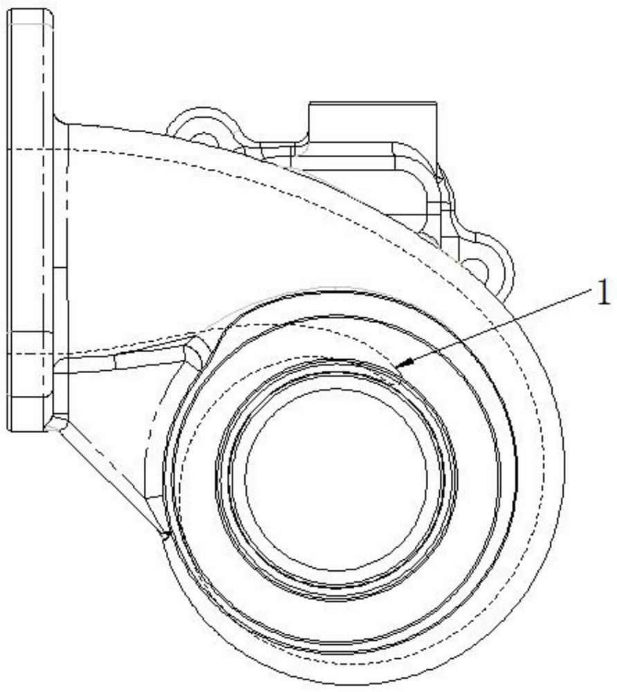
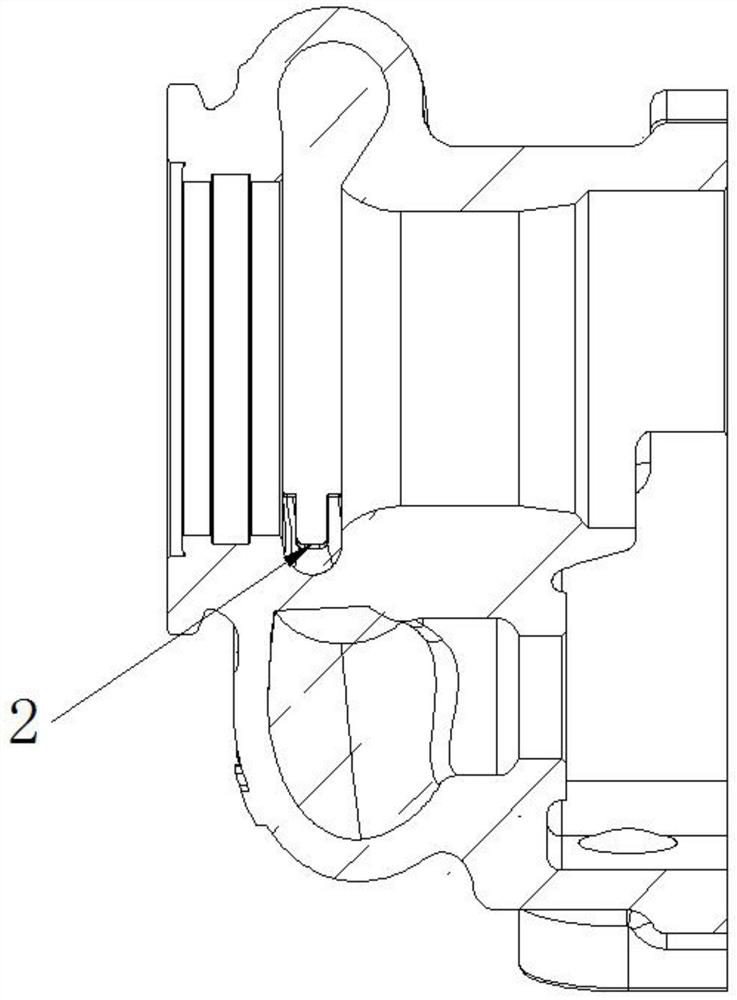
[0049] Such as figure 1 and figure 2 As shown, the mouthpiece structure of the turbine casing includes the mouthpiece, and a diversion groove is opened at the mouthpiece.

[0050] The guide slot includes an intermediate groove structure, which is suitable for large turbochargers.

[0051] The groove width of the middle groove structure is 2-6mm, and the groove depth is 1-15mm.

Embodiment 2

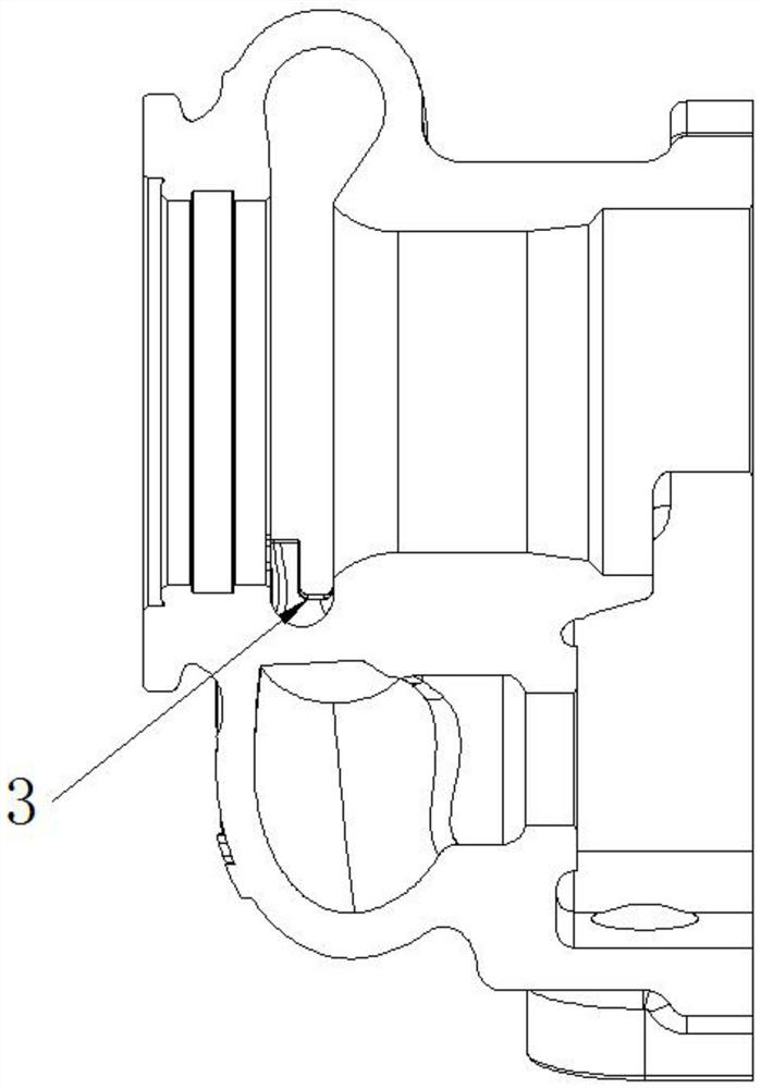
[0053] Such as image 3 and Figure 4 as shown,

[0054] The diversion groove includes a lower groove structure, which is suitable for medium and small turbochargers; the static pressure value of the turbine inlet with the side groove scheme is reduced by about 0.2kPa as a whole, and is improved by about 2.5%; the excitation force of the turbine shell with the original mouthpiece structure is 1700Pa , After optimizing the structure of the mouthpiece, the exciting force of the turbine shell is 1430Pa, and the exciting force of the turbine shell is improved by 15.9%; after optimizing the structure of the mouthpiece, the efficiency of the turbine is increased by about 2%;

[0055] The groove bottom of the lower groove structure is gradually expanded from one side of the groove wall to the other groove wall.

[0056] The groove width of the lower groove structure is 2-6mm, and the groove depth is 1-15mm.

Embodiment 3

[0058] Such as Figure 5 as shown,

[0059] The guide slots include oblique groove structures, which are especially suitable for small turbochargers.

[0060] The inclined groove structure is arranged obliquely on one side of the groove wall near the gas outlet end of the turbine casing.

[0061] The groove depth of the oblique groove structure is 1-15mm, and the slope is 10-60°.

[0062] Such as Figure 7-9 as shown,

[0063] The middle groove structure, the lower groove structure, and the oblique groove structure can obviously improve the BPF noise of the turbine.

[0064] Such as Figure 10-12 as shown,

[0065] The relationship between the pressure amplitude and frequency can be obtained by taking the average value of the turbine inlet static pressure and performing Fourier transform. The pressure amplitude represents the excitation of the airflow to the turbine. The lower the pressure amplitude, the smaller the force of the airflow on the turbine blades, which is m...


PUM

PropertyMeasurementUnit
Groove widthaaaaaaaaaa
Groove depthaaaaaaaaaa
Slopeaaaaaaaaaa

Abstract

The invention relates to the technical field of turbine shell structures, in particular to a turbine shell laryngeal structure which comprises a larynx, and a flow guide groove is formed in the larynx. The turbine shell laryngeal structure solves the problems that in the prior art, due to the fact that static pressure distribution of a turbine rotor inlet annular face near a turbine shell throat is not uniform, thus when turbine blades pass through the throat in the rotating process, large pressure changes occur, a large excitation effect is generated on turbine vibration, the turbine blades vibrate periodically, and turbine end BPF noise is generated; two streams of airflow are sharply mixed near the throat, so that the turbine efficiency is obviously reduced; and due to the fact that the through-flow capacity of the turbine is reduced, the rotating speed of a supercharger is obviously increased when an engine rotates at a low speed.

Description

technical field [0001] The invention relates to the technical field of turbine casing structures, in particular to a turbine casing mouthpiece structure. Background technique [0002] In order to meet the emission requirements, road country 6 and non-road T4 engines use a large proportion of EGR to reduce NOx emissions, and it is generally required to form EGR at around 1400r / min. Significantly reduce PM and smoke requirements, and require improvement of engine low speed and partial load smoke. The medium and low speed torque is obviously improved, the torque reserve coefficient is obviously increased, and higher requirements are put forward for the responsiveness of the supercharger. It is required to significantly improve the engine economy and reduce CO2 emissions, and it is necessary to continue to improve the efficiency of the turbocharger. [0003] The blade passing frequency BPF (blade passing frequency) and its harmonic frequency are defined as f=i*f0*N, where i=1,...

Claims


Application Information

Patent Timeline
IPC IPC(8): F01D25/24F01D25/04F01D25/00F02B37/00
CPCF01D25/00F01D25/04F01D25/24F02B37/00Y02T10/12
Inventor 李伟张健健甄冠富付丽娇刘永芳苗熠芝马饶村
Owner 康跃科技(山东)有限公司
Why Eureka
Try Eureka