Engineering machinery shock absorber and shock absorption method thereof

A technology for construction machinery and shock absorbers, which is applied in the direction of shock absorbers, springs/shock absorbers, chemical instruments and methods, etc., and can solve the problems of easy shock absorption and failure of shock absorbers

Inactive Publication Date: 2021-04-09
梅阵阵
View PDF0 Cites 5 Cited by
  • Summary
  • Abstract
  • Description
  • Claims
  • Application Information

AI Technical Summary

Problems solved by technology

[0004] The purpose of the present invention is to solve the problem that the shock absorber in the prior art is prone to shock absorption failure after running for a long time, and proposes a construction machinery shock absorber and its shock absorption method

Method used


Image

  • Engineering machinery shock absorber and shock absorption method thereof
  • Engineering machinery shock absorber and shock absorption method thereof
  • Engineering machinery shock absorber and shock absorption method thereof

Examples


Embodiment 1

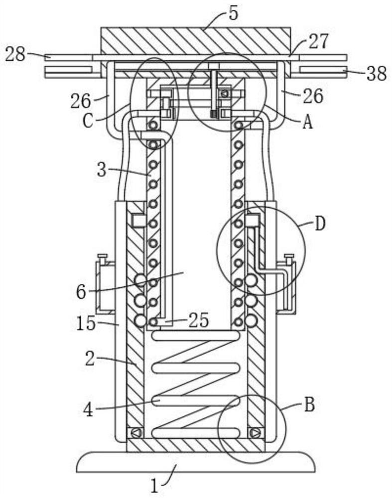
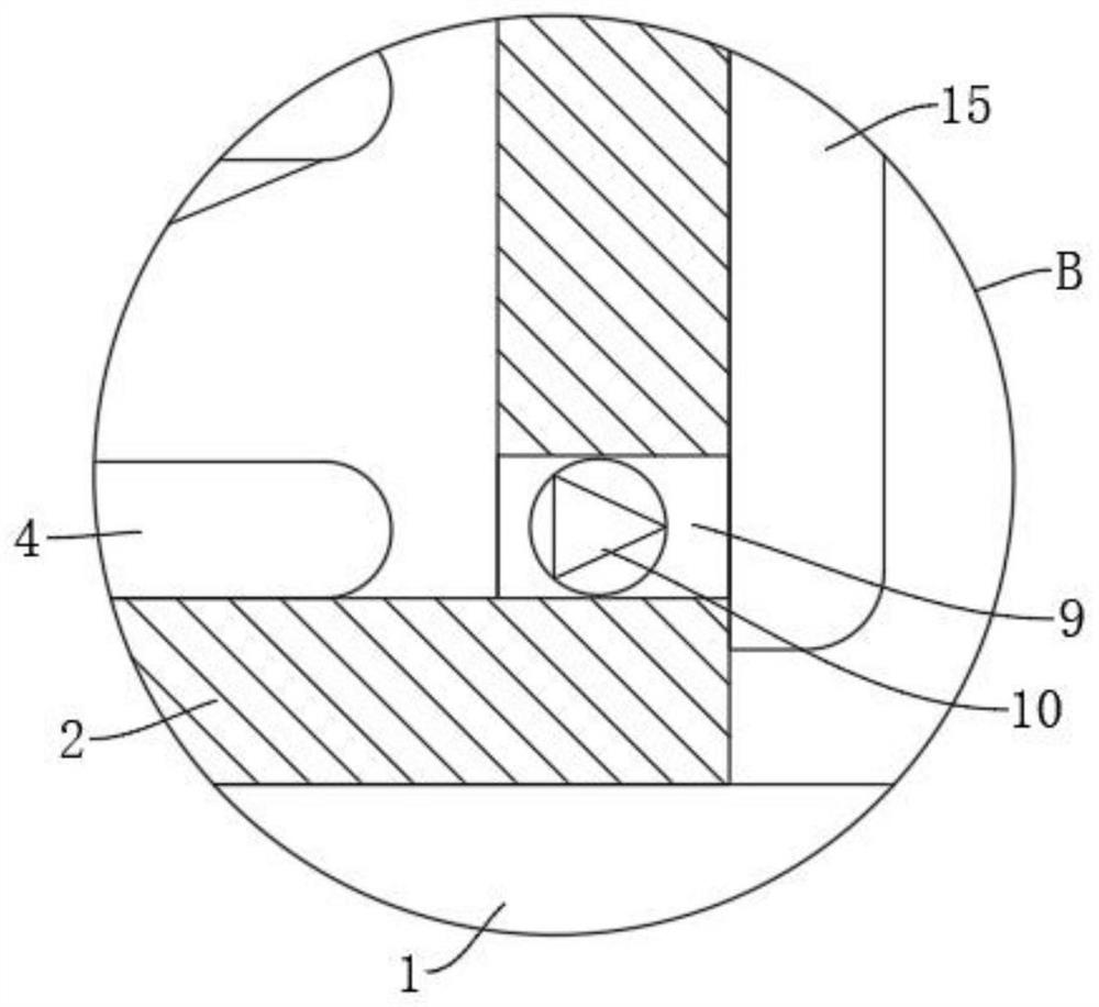
[0040] refer to Figure 1-8 , a shock absorber for construction machinery, comprising a base 1, the upper end of the base 1 is fixedly connected with a buffer sleeve 2, the inner top of the buffer sleeve 2 is provided with a damping slide bar 3 slidingly connected with it, and the damping slide bar 3 is connected with the buffer The inner bottom of the sleeve 2 is elastically connected by a damping spring 4, the upper end of the damping slide bar 3 is fixedly connected with a support plate 5, the lower end of the damping slide bar 3 is provided with a cooling groove 6, and the upper end outer wall of the cooling groove 6 is provided with There are a plurality of suction ports 7 distributed in a circle, dust-proof nets 8 are fixedly installed in the entrances of the plurality of suction ports 7, and the outer wall of the lower end of the buffer sleeve 2 is provided with a plurality of exhaust ports 9 distributed in a circle. The first one-way valve 10 is fixedly installed in ea...

Embodiment 2

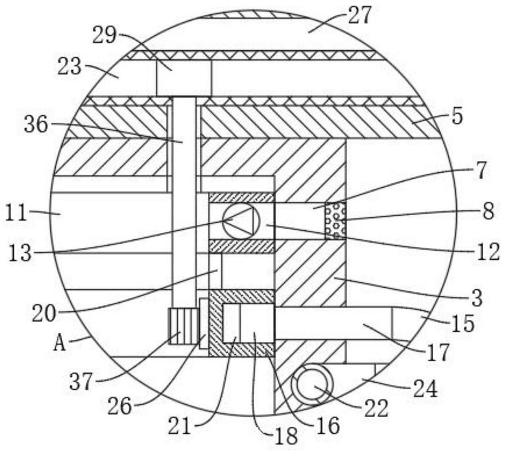
[0043] refer to Figure 1-4 and Image 6 , is basically the same as Embodiment 1, furthermore: the self-cleaning mechanism includes a plurality of air inlets 17 arranged on the outer wall of the shock absorbing slide bar 3, and the plurality of air inlets 17 are respectively connected to the plurality of air inlets through the first hose 15. Two exhaust ports 9 are fixedly connected and communicated, and the inner circumference of the cooling groove 6 is connected to the lower ring 16 by rotation, and the lower ring 16 is fixedly connected to the upper ring 11 through the connecting rod 20, and the outer wall of the lower ring 16 is provided with The annular groove 18 that air hole 17 communicates, the inner top of annular groove 18 is provided with the connecting pipe 19 that extends to the upper end of lower ring 16, the end of connecting pipe 19 is fixedly connected and communicated with blind hole 14, and the inner wall of annular groove 18 is fixedly connected with A plu...

Embodiment 3

[0045] refer to figure 1 , figure 2 , Figure 7 and Figure 8 , which is basically the same as that of Embodiment 1, furthermore: the circulation cooling mechanism includes a helical tube 22 fixedly connected to the inner wall of the shock absorbing slide bar 3, and the two ends of the helical tube 22 are respectively provided with a first inlet 24 and a second inlet 25, The inside of the support plate 5 is fixedly equipped with a curved tube 23, both ends of the curved tube 23 are fixedly connected to the first inlet 24 and the second inlet 25 respectively through the second hose 39, and the upper end of the curved tube 23 is fixedly connected to a The heat dissipation plate 27 on the outer wall of the plate 5, the inner wall of the lower ring 16 is fixedly equipped with a ring gear 26, the inner top of the cooling groove 6 is rotatably connected with a rotating shaft 36, and the lower end of the rotating shaft 36 is fixedly connected with a driven gear 37 meshing with the...


PUM


Abstract

The invention discloses an engineering machinery shock absorber and a shock absorption method thereof, and belongs to the field of engineering machinery. The engineering machinery shock absorber comprises a base; the upper end of the base is fixedly connected with a buffer sleeve; the inner top of the buffer sleeve is provided with a shock absorption sliding rod slidably connected with the buffer sleeve in a sleeved mode; the shock absorption sliding rod is elastically connected with the inner bottom of the buffer sleeve through a shock absorption spring; the upper end of the shock absorption sliding rod is fixedly connected with a supporting plate; aplurality of circumferentially distributed exhaust ports are arranged on the outer wall of the lower end of the buffer sleeve; an upper circular ring corresponding to the exhaust ports is rotatably connected to the inner wall of a heat dissipation groove; a plurality of circumferentially distributed through holes and a blind hole are arranged on the outer wall of the upper circular ring; a self-cleaning mechanism matched with multiple dustproof nets is arranged in the heat dissipation groove; and a circulating heat dissipation mechanism connected with the self-cleaning mechanism is arranged in the inner wall of the shock absorption sliding rod. According to a shock absorption device provided by the invention, heat dissipation of the shock absorption device can be achieved while mechanical equipment is damped, and the situation of shock absorption failures is greatly reduced.

Description

technical field [0001] The invention relates to the technical field of engineering machinery, in particular to an engineering machinery shock absorber and a shock absorbing method thereof. Background technique [0002] Construction machinery is an important part of the equipment industry. In a nutshell, all the mechanical equipment necessary for comprehensive mechanized construction projects required for earthwork construction projects, road surface construction and maintenance, mobile lifting and loading and unloading operations, and various construction projects are called construction machinery. [0003] In the construction of construction machinery, shock absorbers can effectively buffer the vibration of machinery. At present, the widely used shock absorber is spring shock absorber. The spring generates a lot of heat after working for a long time, and it is prone to shock absorption failure, which affects the shock absorption effect of mechanical equipment, and the serv...

Claims


Application Information

Patent Timeline
Patent Type & Authority Applications(China)
IPC IPC(8): F16F13/00F16F9/32F16F9/34F16F9/42B08B5/02
CPCB08B5/02F16F9/3207F16F9/3278F16F9/34F16F9/42F16F13/002
Inventor 梅阵阵
Owner 梅阵阵
Why Eureka
Try Eureka