Detachable deformable gear shifting handle

A shift handle and detachable technology, which is applied in the field of detachable deformable shift handles, can solve the problems of the shift handle not having disassembly and hammering functions, unable to achieve quick disassembly, and poor overall effect, etc. The arm, the overall function is perfect, the effect of strong practicability

Inactive Publication Date: 2021-04-09
汉喜龙汽车零部件(嘉兴)有限公司
View PDF5 Cites 0 Cited by
  • Summary
  • Abstract
  • Description
  • Claims
  • Application Information

AI Technical Summary

Problems solved by technology

[0002] The shift handle set on the car shifter is mostly fixedly connected with the main body, and the two cannot be quickly disassembled
And when the vehicle is in distress and the doors and windows cannot be opened, it is necessary to use a foreign object to break the window glass before escaping. However, the traditional car shift handle does not have the functions of disassembly and hammering, and its use is limited. not effectively

Method used


Image

  • Detachable deformable gear shifting handle
  • Detachable deformable gear shifting handle
  • Detachable deformable gear shifting handle

Examples


Embodiment 1

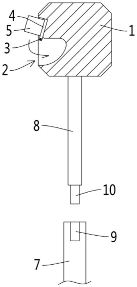
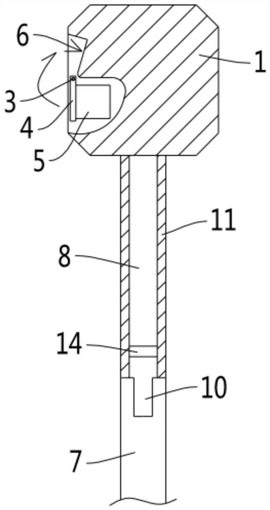
[0018] see figure 1 with figure 2 As shown, a detachable deformable shift handle involved in this embodiment includes a shift lever. One end of the shift lever is connected to the main body of the shifter, and the other end is provided with a shift handle 1 for gripping. The side of described shifting handball 1 is dug with hammerhead groove 2, is connected with rotating shaft 3 on the groove wall of hammerhead groove 2, and rotating shaft 3 is provided with the hammerhead seat 4 that rotates with it, and hammerhead seat 4 is provided with Hammer head 5, the shifting hand ball 1 is provided with a supporting platform 6 located in the hammer head groove 2, when the hammer head 5 rotates outside the hammer head groove 2, the hammer head seat 4 is against the bearing Stand 6; the shift lever is composed of a fixed lower rod 7 and a movable upper rod 8, the end surface of the fixed lower rod 7 facing the movable upper rod 8 is provided with a threaded hole 9, and the movable upp...

Embodiment 2

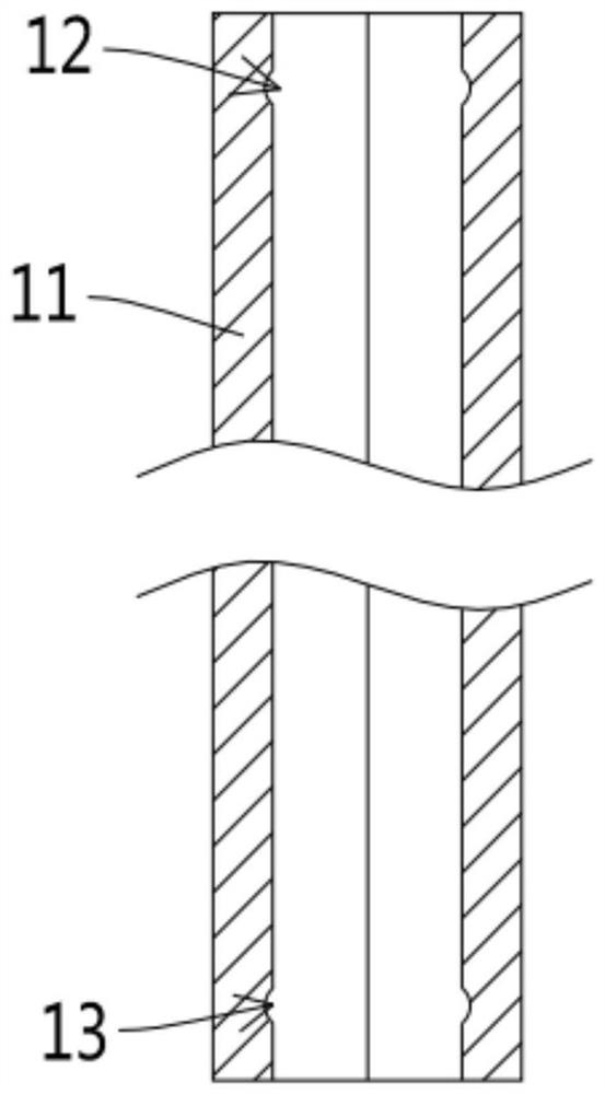
[0023] see Figures 1 to 5 As shown, a detachable deformable shift handle involved in this embodiment is further set on the basis of Embodiment 1, and the movable upper rod 8 is slidably connected with an extension sleeve 11, and the extension sleeve The inner pipe wall of the pipe 11 is dug with an upper limit groove 12 near one end and a lower limit groove 13 near the other end; the movable upper rod 8 is provided with side holes 14 at both ends communicating with the outside world, and the side holes 14 The axis of the shaft is perpendicular to the extending direction of the length of the movable upper rod 8, the steel ball 15 partially exposed in the side hole 14 is provided, and one end of the steel ball 15 is provided with a limiter that restricts it from rolling out of the side hole 14 completely. The other end of the position ring 16 has an elastic body 17 against the steel ball 15 , and the steel ball 15 partially exposed from the opening is embedded in the upper limi...

Embodiment 3

[0027] see Figures 1 to 5 As shown, a detachable deformable shift handle involved in this embodiment, on the basis of Embodiment 2, is further set as follows: a guide groove 18 is opened on the movable upper rod 8, and a guide groove 18 is opened on the guide groove 18 The length extension direction is the same as the length extension direction of the movable upper rod 8 , and a guide rail 19 arranged on the inner wall of the extension sleeve 11 is slidably connected to the guide groove 18 .

[0028] Preferably, the cross-sectional shape of the movable upper rod 8 is a regular hexagon; the inner hole of the extension sleeve 11 matches the movable upper rod 8 .

[0029] In this embodiment, the arrangement of the guide groove 18 and the guide rail 19 plays a role of sliding guide.

[0030] The detachable deformable shift handle involved in the present invention can be used as a hammer to strike the shift handle by removing the shift handle from the shifter main body and turnin...


PUM


Abstract

The invention discloses a detachable deformable gear shifting handle which comprises a gear shifting rod, a gear shifting handball is arranged at one end of the gear shifting rod, a hammer head groove is dug in the side face of the gear shifting handball, a rotating shaft is rotatably connected to the groove wall of the hammer head groove, a hammer head base is arranged on the rotating shaft, a hammering head is arranged on the hammer head base, and a bearing table located in the hammer head groove is arranged on the gear shifting handball; and the gear shifting rod is composed of a fixed lower rod and a movable upper rod, a threaded hole is formed in the end face, facing the movable upper rod, of the fixed lower rod, a stud part in threaded connection into the threaded hole is arranged on the end face, facing the fixed lower rod, of the movable upper rod, and the movable upper rod is in threaded connection onto the fixed lower rod. According to the gear shifting handle, under the condition that a vehicle is in emergency, the gear shifting handle can be detached from a gear shifter body, the hammering head is rotated out of the hammer head groove to serve as a hammer to knock window glass to realize escape; and the length of the movable upper rod serving as the hammer handle part can be adjusted, and a force application arm is prolonged, so that the hammering is more labor-saving.

Description

technical field [0001] The invention relates to the technical field of auto parts, more specifically, it relates to a detachable deformable shift handle. Background technique [0002] The shift handle arranged on the car shifter is mostly fixedly connected to the main body, and the two cannot be quickly disassembled. And when the vehicle is in distress and the doors and windows cannot be opened, it is necessary to use a foreign object to break the window glass before escaping. However, the traditional car shift handle does not have the functions of disassembly and hammering, and its use is limited. not effectively. Accordingly, the present invention proposes a detachable deformable shift handle. Contents of the invention [0003] The object of the present invention is to overcome the shortcomings of the above-mentioned prior art and provide a detachable deformable shift handle. [0004] In order to solve the above-mentioned technical problems, the object of the present ...

Claims


Application Information

Patent Timeline
Patent Type & Authority Applications(China)
IPC IPC(8): F16H59/02B60R21/02
CPCB60R21/02F16H59/0278
Inventor 张汉镇
Owner 汉喜龙汽车零部件(嘉兴)有限公司
Why Eureka
Try Eureka