
Device for laying mains pipes

A pipeline and pipeline technology, applied in the field of pipeline pipeline laying equipment, can solve the problems of heavy equipment weight and high cost

Active Publication Date: 2021-04-09
아씨멕스
View PDF8 Cites 3 Cited by
  • Summary
  • Abstract
  • Description
  • Claims
  • Application Information

AI Technical Summary

Problems solved by technology

[0012]This results in a high weight of the equipment and a high cost due to the necessary oversize

Method used


Image

  • Device for laying mains pipes
  • Device for laying mains pipes
  • Device for laying mains pipes

Examples


Embodiment Construction

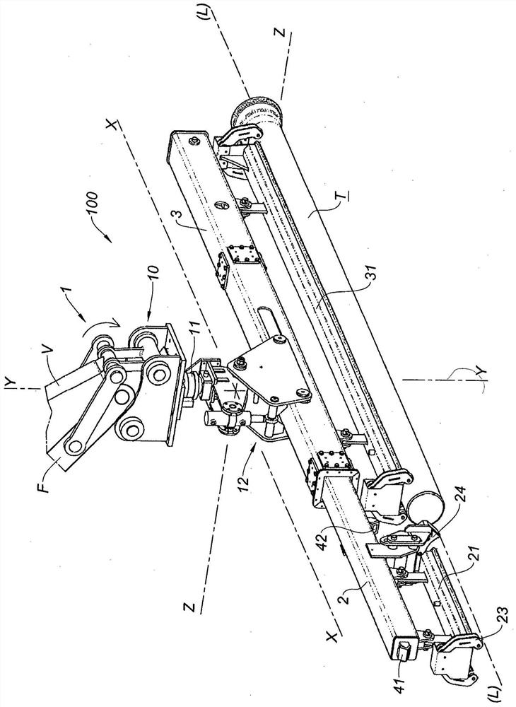
[0065] according to figure 1 , the present invention is directed to a laying device 100 for laying piping elements (pipe T). The device is carried by an articulated arm F equipped with a jack V of a public works machine. The pipeline T carried by the equipment 100 should be laid and connected to the laid pipeline To, which is usually located at the bottom of the trench.

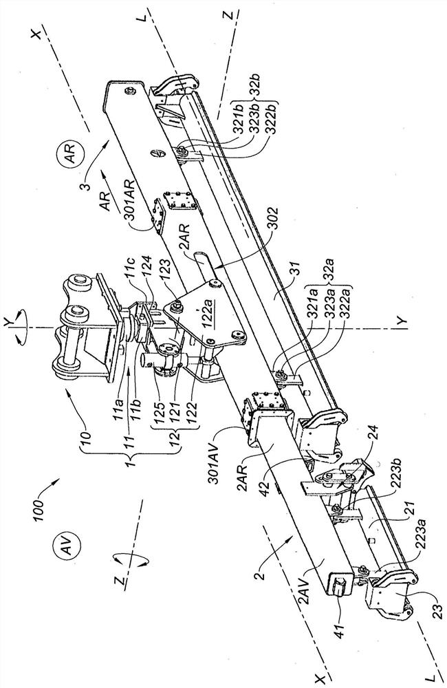
[0066] For ease of description, an orthogonal reference frame X, Y, Z related to the device 100 will be used to define the different directions controlled by the operator of the device 100 using the joystick; The data of the environment (that is, the trench) are controlled; these data are displayed on the screen associated with the device 100, and the screen displays the position measurement of the laid pipeline To by the cameras 41, 42 equipped with the device 100. Therefore, firstly, by means of the front camera 41, the pipeline T to be laid is positioned on the axis of the laid pipeline To, and then by m...


PUM


Abstract

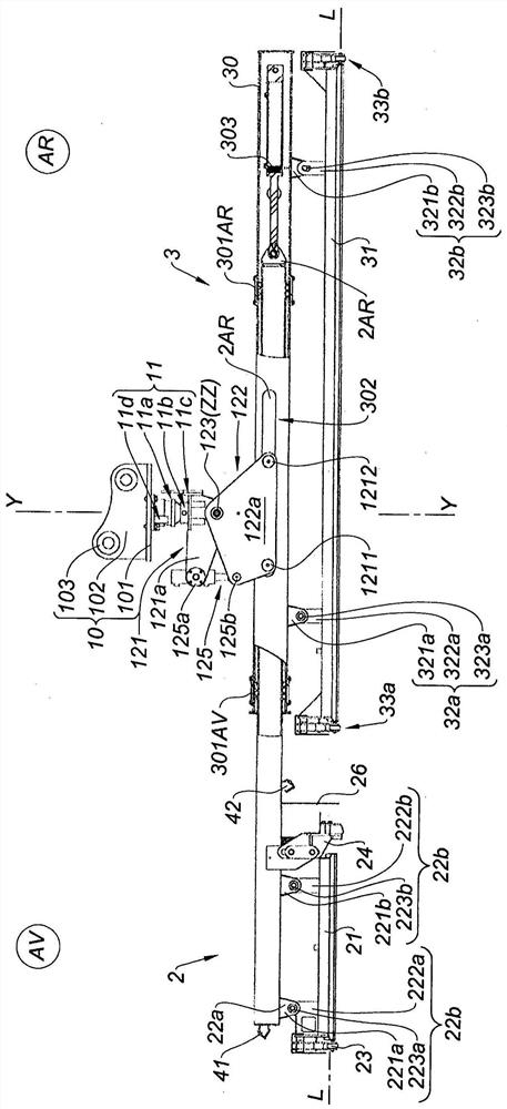
Disclosed is a device for laying mains pipes (T), connected to the boom (F) of a transport machine carrying the pipe to be laid (T) in order to fit it into a pipe (To) that is already laid. This attachment head (1) is formed by a pivoting joint (11) with a vertical axis (YY) and a tilting joint (12) with a horizontal axis (Z). The device comprises a guide rail (2) having a support (21) for positioning the guide rail on, and fastening it to, the end of the laid pipe (To), and for aligning the pipe to be laid (T) with the pipe (To) already laid, as well as a carriage (3) formed of a telescopic tube (30) fitted on the guide rail (2) and actuated with respect to same; the carriage (3) carries the pipe (T) that is to be positioned and connected to the laid pipe (To) by fitting it into said laid pipe (To). The guide rail (2) is connected to the attachment head (1) through the telescopic tube (30).

Description

technical field [0001] The invention relates to a pipeline laying equipment, which is connected to the arm of a transport machine, carries the pipeline to be laid so as to assemble the pipeline to be laid into the laid pipeline, and the pipeline pipeline laying equipment comprises: [0002] a tightening head comprising a pivot joint with a vertical axis and a tilt joint with a horizontal axis, [0003] rail, the rail has: [0004] a support for positioning and securing to the end of the laid pipe and for aligning the pipe to be laid with the laid pipe, [0005] Bench, comprising telescoping tubes mounted on and actuated relative to guide rails, provided with supports, the supports of the bench carrying the pipeline to be laid to be positioned and fitted into the end slots of the already laid pipeline . Background technique [0006] According to document FR 2 932 240, it is known to lay pipelines by means of a laying device 1 mounted on the articulated arm 2 of a hoisting ...

Claims


Application Information

Patent Timeline
IPC IPC(8): F16L1/036B25B11/00B66C1/02F16L1/06F16L1/09F16L1/10F16L1/11B25B27/16
CPCF16L1/036F16L1/065F16L1/09F16L1/10F16L1/11B25B27/16B66C1/0243B66C1/68B66C23/44B66C1/0287F16L1/028
Inventor P·雷纳德J·德恩
Owner 아씨멕스
Learn More