Water filtering and residue discharging structure and dish-washing machine with same

A technology for water filtering and slag discharge, which is applied in the fields of filtration and separation, fixed filter element filters, chemical instruments and methods, etc. It can solve the problems of incapable of automatic slag discharge and can only manually clean the residue, etc., and achieve the effect of automatic slag discharge.

Pending Publication Date: 2021-04-13
湖南美佳电器有限公司
View PDF3 Cites 0 Cited by
  • Summary
  • Abstract
  • Description
  • Claims
  • Application Information

AI Technical Summary

Problems solved by technology

[0006] The purpose of the present invention is mainly to solve the disadvantages in the prior art that the filter screen is installed at the bottom or top for filtering, and the residue can only be manually cleaned and / or cannot be automatically discharged, and a dishwasher is proposed dish rack

Method used


Image

  • Water filtering and residue discharging structure and dish-washing machine with same
  • Water filtering and residue discharging structure and dish-washing machine with same

Examples


Embodiment 1

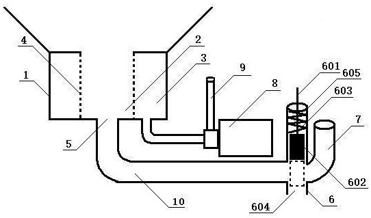
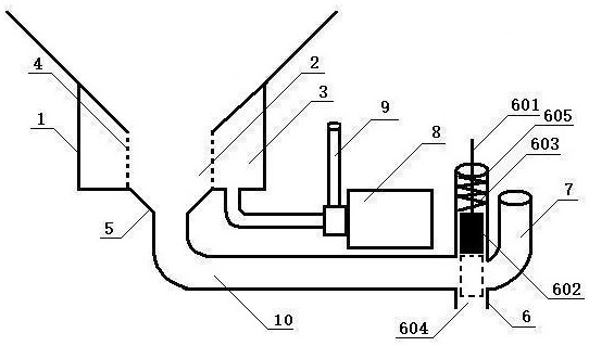
[0031] A water filtration and slag discharge structure, comprising a water storage part 1, a filter screen 4 and a slag discharge port 5, the water storage part 1 is provided with a filter screen 4, the filter screen 4 forms a water filter part 2, the filter screen 4 and the water storage A water purification part 3 is formed between the parts 1, and a slag outlet 5 is provided at the bottom opening of the water filtering part 2; the filter screen 4 is in a cylindrical structure or a square structure, and the filter screen 4 is arranged in the middle of the water storage part 1, The filter screen 4 forms the water purification part around.

Embodiment 2

[0033] The water filtration and slag discharge structure as described in Embodiment 1 also includes a sewage discharge pipe 10, a sewage discharge valve 6 and an exhaust pipe 7 in the machine. In-machine exhaust pipe 7; the filter screen 4 is in a cylindrical structure or a square structure, and the filter screen 4 is arranged in the middle of the water storage part 1, and the water purification part is formed around the filter screen 4.

Embodiment 3

[0035] As in the water filtration and slag discharge structure described in Embodiment 1 or 2, the sewage valve 6 is composed of a gate valve pull rod 601, a water blocking rubber plug 602, a spring 603 and a sewage outlet 604. The front end of the gate valve pull rod 601 is covered with a spring 603, and the gate valve pull rod 601 The rear end is provided with a water blocking rubber plug 602, and the gate valve pull rod 601, spring 603 and water blocking rubber plug 602 move in the sewage valve body 605; the filter screen 4 is in a cylindrical or square structure, and the filter screen 4 is arranged on In the middle of the water storage part 1, the water purification part is formed around the filter screen 4.


PUM


Abstract

The invention discloses a water filtering and residue discharging structure which comprises a water storage part, a filter screen and a residue discharging opening. The filter screen is arranged in the water storage part, a water filtering part is formed in the filter screen, a water purifying part is formed between the filter screen and the water storage part, and the residue discharging opening is formed in an opening in the bottom of the water filtering part. The problem that an existing filter screen is installed at the bottom or the top for filtering, residues can only be cleaned manually, and / or automatic residue discharging cannot be achieved is mainly solved. Compared with the prior art, the invention discloses a dish rack of a dish washing machine, which has the following beneficial effects that 1, an existing filter screen is mounted at the bottom or the top for filtering, residues can only be cleaned manually, and automatic residue discharging cannot be achieved, however, the filter screen of the invention carries out filtering from the periphery, and residues are discharged from the bottom; 2, automatic residue discharging can be realized; and 3, the filter screen does not need to be cleaned.

Description

technical field [0001] The invention relates to the technical field of slag discharge for dishwashers, in particular to a structure for filtering water and slag discharge and a dishwasher with the structure. Background technique [0002] For example, Chinese patent CN201820015204.6 discloses that the pre-filter 7 is arranged at the bottom for bottom filtration, and the residue after cleaning needs to be cleaned manually. [0003] For example, the Chinese patent CN201310556627.0 discloses the filter 2, which also performs bottom filtration at the bottom, and the residue after cleaning needs to be manually cleaned. [0004] For example, Chinese patent CN201910484712.8 discloses a filter plate 13. The filter plate 13 filters and cleans the residue on the upper part of the water tank 12. The upper end of the filter plate 13 is sunken inward, and the residue will not be concentrated at the edge but more concentrated in the depression. , Need to manually clean up the residue afte...

Claims


Application Information

Patent Timeline
IPC IPC(8): B01D29/11
CPCB01D29/018
Inventor 李前春
Owner 湖南美佳电器有限公司
Why Eureka
Try Eureka