Workshop transportation robot and transportation method
A robot and workshop technology, applied in transportation and packaging, motor vehicles, trolleys, etc., can solve the problems of poor actual use effect of equipment, effective adjustment of use direction, inconvenient loading and unloading, etc.
- Summary
- Abstract
- Description
- Claims
- Application Information
AI Technical Summary
Problems solved by technology
Method used
Image
Examples
Embodiment 1
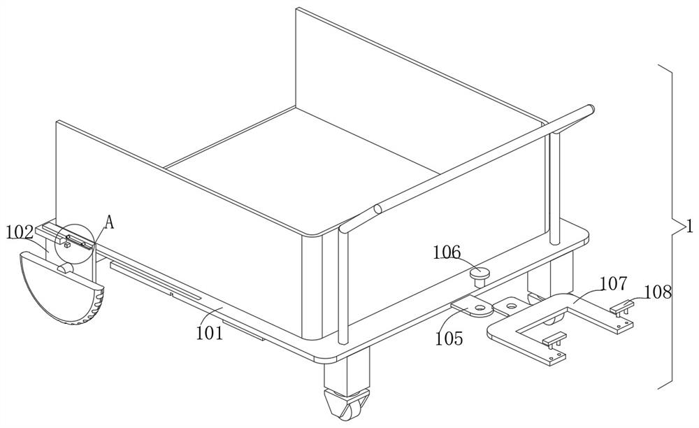
[0028] Embodiment one, with reference to Figure 1-9A transportation robot for a workshop, including a storage mechanism 1, a guide mechanism 2 and a ground body 3, the guide mechanism 2 is arranged on the top of the ground body 3, the storage mechanism 1 is also arranged on the top of the ground body 3, and the guide mechanism 2 includes two installations Frame 202 and mobile frame 210, the establishment of installation frame 202 facilitates the installation and setting of other functional components of the equipment, the establishment of mobile frame 210 facilitates the installation and setting of other functional components of the equipment, and the center of the top of each installation frame 202 is provided with an installation slot , the establishment of the installation groove is convenient for the installation of the installation frame 202, and the threaded rod 203 is fixedly connected between the center of the inner surface wall on both sides of each installation groov...
Embodiment 2
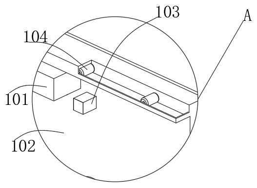
[0029] Embodiment two, refer to Figure 2-9 The outer surface of one side of each support frame 204 slides through to the bottom of the corresponding guide rail 208, the two sides of the bottom center of the moving frame 210 are fixedly connected with the connecting frame 211, and the bottom end of each limit rod 216 slides through the limit tube 213 On the inner bottom surface, the inner surface walls on both sides of each installation frame 202 are fixedly connected with the limit strips 209 near the top edge, and the outer surfaces on both sides of the car body 101 are located on the side of the corresponding adjustment groove. There are two, the outer surfaces on both sides of the mobile frame 102 are located in the two positioning openings and are fixedly connected with the adjustment block 103, the top of the connecting frame 107 is slidingly embedded with limit bolts 108 near the edges of both ends, and the center of the top of the ground body 3 There are slots on both ...
PUM
 Abstract
Description
Claims
Application Information
 - R&D
- Intellectual Property
- Life Sciences
- Materials
- Tech Scout
- Unparalleled Data Quality
- Higher Quality Content
- 60% Fewer Hallucinations
Browse by: Latest US Patents, China's latest patents, Technical Efficacy Thesaurus, Application Domain, Technology Topic, Popular Technical Reports.
© 2025 PatSnap. All rights reserved.Legal|Privacy policy|Modern Slavery Act Transparency Statement|Sitemap|About US| Contact US: help@patsnap.com


