A road marking equipment for road surface printing
A technology for marking lines and roads, applied in roads, roads, road repairs, etc., can solve the problems of low efficiency and low accuracy of manual printing marking lines, achieve high accuracy, improve work efficiency, and prevent movement
- Summary
- Abstract
- Description
- Claims
- Application Information
AI Technical Summary
Problems solved by technology
Method used
Image

Examples
Embodiment 1
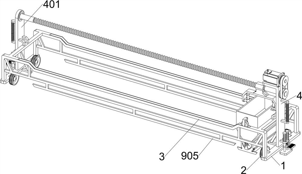
[0064] A road surface printing marking equipment, such as figure 1 As shown, it includes a supporting plate 1, a roller 2, a connecting frame 3, a first supporting frame 4, a second supporting frame 401, a handle 5, a servo motor 6, a driving component 7, a moving component 8, a blanking component 9 and a printing component 10. Supporting plates 1 are provided on the left and right sides of the bottom of the connecting frame 3. The supporting plates 1 are provided with rollers 2 in front and rear symmetrical rotation. A second support frame 401 is provided in the middle of the top of the board 1, a handle 5 is provided on the upper part of the side of the first support frame 4 and the second support frame 401 away from each other, and a servo motor 6 is provided on the top of the first support frame 4. The first support frame 4 and the upper part of the second support frame 401 is provided with a driving component 7, between the connecting frame 3 and the driving component 7 i...
Embodiment 2
[0067] On the basis of Example 1, as figure 1 , figure 2 and image 3 As shown, the drive assembly 7 includes a transmission wheel 701, a screw rod 702, a belt 703, a first nut 704 and a movable frame 705. A screw rod 702 is rotatably provided between the upper part of the first support frame 4 and the upper part of the second support frame 401 , the output shaft of the servo motor 6 and the right part of the screw rod 702 are provided with a transmission wheel 701, a belt 703 is provided between the transmission wheels 701, a first nut 704 is threaded on the screw rod 702, and the bottom of the first nut 704 is provided with Mobile rack 705.
[0068] When people start the servo motor 6, they control the servo motor 6 to rotate forward, the output shaft of the servo motor 6 drives the upper transmission wheel 701 to rotate, thereby driving the belt 703 and the lower transmission wheel 701 to rotate, and the lower transmission wheel 701 drives the wire The rod 702 rotates, ...
Embodiment 3
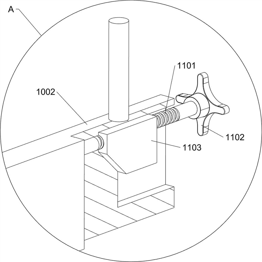
[0074] On the basis of Example 2, as image 3 , Figure 4 , Figure 5 and Image 6 As shown, the printing assembly 10 includes a fixing frame 1001, a scraper 1002 and a first spring 1003, a fixing frame 1001 is arranged at the lower part of the outer side of the storage frame 801, and a scraper 1002 is slidably arranged at the lower part of the left and right sides of the fixing frame 1001 to scrape the material. A first spring 1003 is provided between the upper, front and rear sides of the upper portion of the plate 1002 and the bottom of the fixing frame 1001 .
[0075] When the storage frame 801 moves downward, it drives the fixed frame 1001, the scraper 1002 and the first spring 1003 to move downward. When the fixed frame 1001 contacts the road, the storage frame 801 stops moving downward, and at the same time the storage frame 801 When moving to the left, it drives the fixed frame 1001, the scraper 1002 and the first spring 1003 to move to the left, and then the scrape...
PUM
 Abstract
Description
Claims
Application Information