
Indoor illuminating lamp capable of adjusting light

A lighting and light technology, applied in lighting devices, lighting auxiliary devices, fixed lighting devices, etc., can solve the problems of troublesome replacement and cleaning process, easy to cause danger, difficult to clean and replace, etc., to reduce the trouble of cleaning, The effect of reducing the trouble of operation and reducing the trouble

Active Publication Date: 2021-04-13
SHENZHEN FLASHINE LIGHTING CO LTD
View PDF10 Cites 1 Cited by
  • Summary
  • Abstract
  • Description
  • Claims
  • Application Information

AI Technical Summary

Problems solved by technology

[0003] Ordinary indoor lighting is hung on the ceiling, so it is difficult to clean and replace. Generally, the lighting can only produce one kind of light. When it is necessary to adjust the light or clean the lighting, the user needs to climb up the ladder to replace the lighting. Or the process of cleaning, replacing and cleaning is cumbersome and prone to danger

Method used


Image

  • Indoor illuminating lamp capable of adjusting light
  • Indoor illuminating lamp capable of adjusting light
  • Indoor illuminating lamp capable of adjusting light

Examples


Embodiment 1

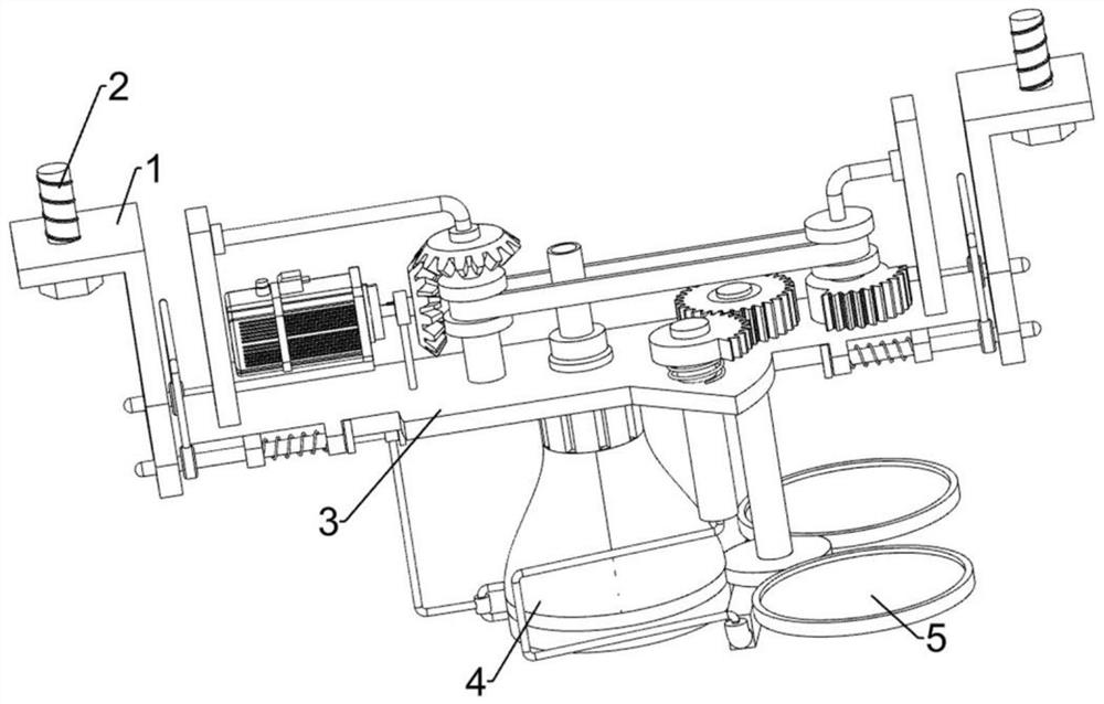
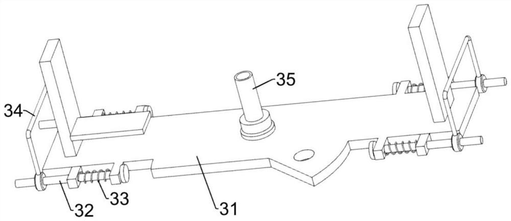
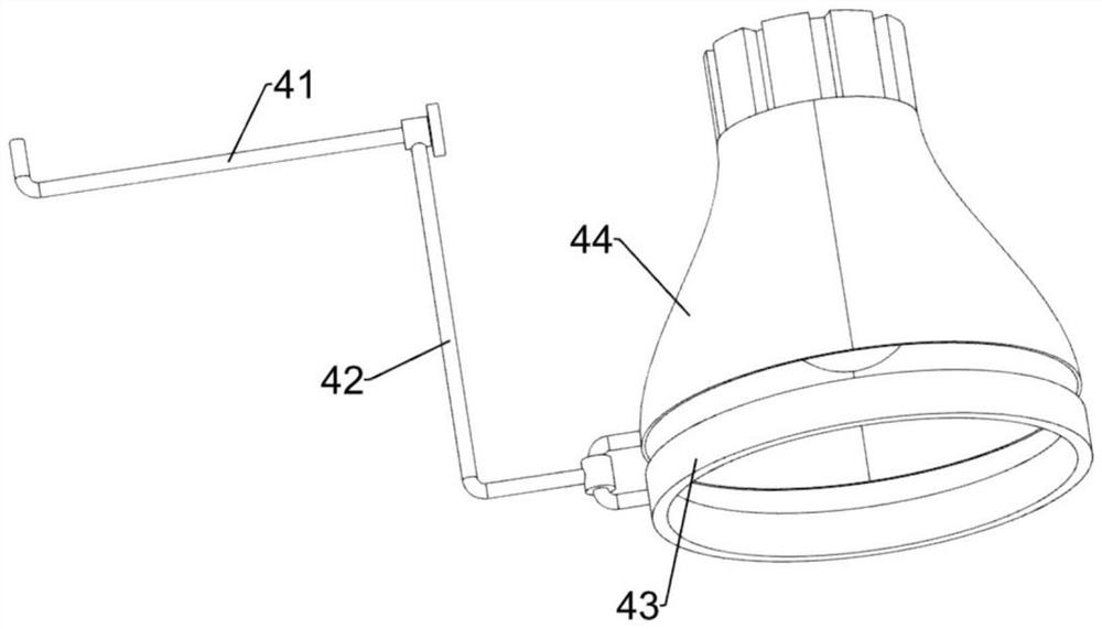
[0025] A dimmable interior light such as Figure 1-4 As shown, it includes a fixed frame 1, a bolt 2, an installation component 3, a moving component 4 and an adjustment component 5, and the fixed frames 1 on the left and right sides are connected with bolts 2 through threads, and the fixed frames 1 on the left and right sides are slidingly arranged. There is an installation assembly 3, the lower side of the installation assembly 3 is provided with a moving assembly 4, and the installation assembly 3 is rotatably provided with an adjustment assembly 5.

[0026] When the device needs to be used, install the fixing frames 1 on both sides on the ceiling through bolts 2, and then control the installation components 3 so that the installation components 3 are installed between the fixing frames 1, and then control the moving components 4 after installation, so that The moving assembly 4 is used for lighting. When the light needs to be adjusted, the adjusting assembly 5 can be contr...

Embodiment 2

[0034] On the basis of Example 1, such as Figure 4 and Figure 5 Shown, also comprise motor 6, bevel gear combination 7, flat belt combination 8, the first missing gear 9 and common gear 10, the left part upper side of the first mount 31 is provided with motor 6, the output shaft of motor 6 and Bevel gear combination 7 is connected between the first mounting frame 31, and bevel gear combination 7 is connected with the first mounting frame 31 rotationally, and flat belt combination 8 is connected between bevel gear combination 7 and the first mounting frame 31, and flat belt Combination 8 is connected with the first installation frame 31 rotationally, and the lower side of the right part of flat belt combination 8 is connected with the first missing gear 9, and the upper side of the second installation frame 51 is connected with ordinary gear 10 by overrunning clutch, and ordinary gear 10 and The first missing gear 9 meshes.

[0035] When the light needs to be adjusted, the ...


PUM


Abstract

The invention relates to an illuminating lamp, in particular to an indoor illuminating lamp capable of adjusting light. The technical problem to be solved by the invention is to provide the indoor illuminating lamp capable of adjusting the light rays, which can automatically adjust the light rays and clean the illuminating lamp. The indoor illuminating lamp capable of adjusting light comprises fixing frames; bolts mounted on the fixing frames on the two sides; a mounting assembly mounted between the fixing frames on the two sides in a sliding manner; a moving assembly mounted on the mounting assembly; and an adjusting assembly rotatably mounted on the mounting assembly. Three light filtering plates are arranged, so that a user has more choices, more scene requirements are met, and the trouble of configuring various illuminating lamps is reduced; the illuminating lamp is provided with a motor, the device can be controlled by controlling the motor, manual control by a user is not needed, adjustment by the user is more convenient, and the operation trouble of the user is reduced.

Description

technical field [0001] The invention relates to an illuminating lamp, in particular to an indoor illuminating lamp with adjustable light. Background technique [0002] Lighting lamps are a common lighting tool in life. With the development of society, people have many requirements for the shape and performance of lighting lamps. [0003] Ordinary indoor lighting is hung on the ceiling, so it is difficult to clean and replace. Generally, the lighting can only produce one kind of light. When it is necessary to adjust the light or clean the lighting, the user needs to climb up the ladder to replace the lighting. Or the process of cleaning, replacing and cleaning is cumbersome and prone to danger. [0004] Therefore need to design a kind of adjustable light indoor lighting that can automatically adjust the light and clean the lighting lamp. Contents of the invention [0005] In order to overcome the disadvantage that general indoor lighting lamps are difficult to clean and r...

Claims


Application Information

Patent Timeline
Patent Type & Authority Applications(China)
IPC IPC(8): F21S8/00F21V9/08F21V14/08F21V21/02F21V23/00B08B1/02B08B1/20
CPCF21S8/00F21V9/08F21V14/08F21V21/02F21V23/00B08B1/10B08B1/20
Inventor 方弄璋
Owner SHENZHEN FLASHINE LIGHTING CO LTD
Learn More