
Surface plasmon coupled emission directional enhanced microscopic fluorescence imaging and spectral detection method and device based on objective lens coupling

A technology of surface plasmon and microfluorescence, which is applied in the field of microscopic optical imaging and spectral analysis, can solve the problems of large detection range, inability to detect samples, and inability to obtain sample spectral information, so as to achieve simple collection methods, improve collection efficiency and Effect of Detection Sensitivity

Active Publication Date: 2022-05-13
XIAMEN UNIV
View PDF3 Cites 0 Cited by
  • Summary
  • Abstract
  • Description
  • Claims
  • Application Information

AI Technical Summary

Problems solved by technology

At present, although the SPCE imaging and spectral detection device based on the prism configuration can obtain the SPCE fluorescence imaging and spectral information of the sample at the same time, its detection range is large, and it cannot detect samples with a micro-area size, which limits the application of SPCE analysis technology in more Applications on a Small Scale
On the other hand, although the SPCE technology based on the configuration of the objective lens can obtain the imaging information of the micro-scale sample, it is still unable to obtain the spectral information of the corresponding micro-area of ​​the sample.

Method used


Image

  • Surface plasmon coupled emission directional enhanced microscopic fluorescence imaging and spectral detection method and device based on objective lens coupling
  • Surface plasmon coupled emission directional enhanced microscopic fluorescence imaging and spectral detection method and device based on objective lens coupling
  • Surface plasmon coupled emission directional enhanced microscopic fluorescence imaging and spectral detection method and device based on objective lens coupling

Examples


Embodiment

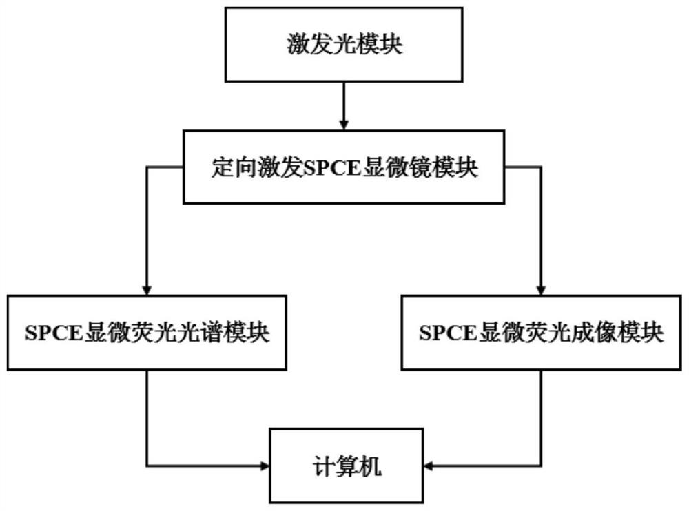
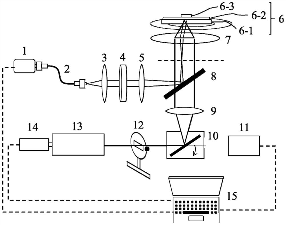
[0049] Please check figure 1 and figure 2 , is a kind of SPCE directional enhanced micro-fluorescence imaging and spectral detection device based on the objective lens coupling type of this embodiment, which includes: excitation light module, directional excitation SPCE microscope module, SPCE micro-fluorescence imaging module, SPCE micro-fluorescence Spectrum module.

[0050] The excitation light module includes a laser 1 and a fiber coupler 2 connected to each other; the excitation beam emitted by the excitation light module travels along the first optical path direction;

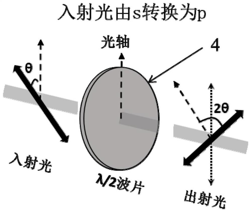
[0051] The directional excitation SPCE microscope module includes a collimating lens 3, a half-wave plate 4, a first focusing lens 5, a sample 6, an objective lens 7, a dichroic filter 8, a second focusing lens 9, and a 90° adjustable total reflection mirror 10; the half-wave plate 4 can adjust the polarization of the excitation light to p polarization, such as image 3 The sample 6 is placed on the s...


PUM


Abstract

The invention discloses a surface plasmon coupled emission (SPCE) directional enhanced microscopic fluorescence imaging and spectral detection method and device based on an objective lens coupling type. The polarized excitation light modulated by a half-wave plate is reflected by a dichroic filter to Arriving at the objective lens at a specific angle, exciting the metal surface plasmon to couple with the sample, the generated SPCE signal is collected by the objective lens and filtered by a dichroic filter, and then imported into the SPCE microfluorescence imaging module or SPCE microfluorescence spectrum through the mirror switch The module realizes the acquisition of SPCE microscopic fluorescence imaging and spectrum of the same micro-area of ​​the sample. In the present invention, by combining the microscope system, the coupling strategy SPCE is applied to high-spatial-resolution fluorescence imaging and spectroscopy at the same time. It has directional enhancement characteristics and a spatial selection function on the micro-area scale, and can obtain high-quality micro-fluorescence imaging and spectroscopy of the same micro-area of ​​the sample. Spectral information provides an efficient and reliable means for detecting low-content components in micro-regions of interest in complex systems.

Description

technical field [0001] The invention relates to the technical field of microscopic optical imaging and spectral analysis, in particular to a method and device for directional enhanced microscopic fluorescence imaging and spectral detection based on surface plasmon coupled emission (SPCE). Background technique [0002] With the continuous development of cells and small molecules in the fields of biology and medicine, it also puts forward higher requirements for microscopic analysis. The microscopic imaging and spectroscopy device is a fusion of optical imaging technology and spectroscopy technology. It can not only provide spatial imaging information of the target object, but also provide rich spectral information, providing a new technical means for studying or observing tiny objects. Fluorescence technology has the advantages of fast imaging speed, good repeatability, and intuitive observation, and has been more and more widely used in the fields of cells and small molecule...

Claims


Application Information

Patent Timeline
Patent Type & Authority Patents(China)
IPC IPC(8): G01N21/01G01N21/64
CPCG01N21/01G01N21/6402
Inventor 李耀群潘晓会徐子谦陈敏曹烁晖
Owner XIAMEN UNIV
Learn More