Silicon micro-strip detection system

A detection system, silicon micro technology, applied in the direction of measuring devices, radiation measurement, radiation intensity measurement, etc., can solve the problems of increasing the weight and high price of aerospace equipment, and achieve the reduction of the occupied area, the reduction of the area, and the reading of the value Precise and stable effect

Active Publication Date: 2021-04-13
NAT SPACE SCI CENT CAS
View PDF5 Cites 3 Cited by
  • Summary
  • Abstract
  • Description
  • Claims
  • Application Information

AI Technical Summary

Benefits of technology

This technology allows for precise and reliable detection of particles with low energies (<1 Gigray). It involves converting signals from analog into digital form before sending them over long distances without occupying too much space on their own devices. By doing this, we can make better detectors that are able to handle higher levels of radiation exposure while still being small enough.

Problems solved by technology

This patented technical problem addressed in this patents relates to improving the accuracy and reliability of detecting events that cause damage or failure in an aircraft's electrical systems without increasing its size and costly replacement costs associated with conventional methods like SEUs.

Method used


Image

  • Silicon micro-strip detection system
  • Silicon micro-strip detection system
  • Silicon micro-strip detection system

Examples


Embodiment Construction

[0038] The technical solution of the present invention will be described in detail below in conjunction with the accompanying drawings.

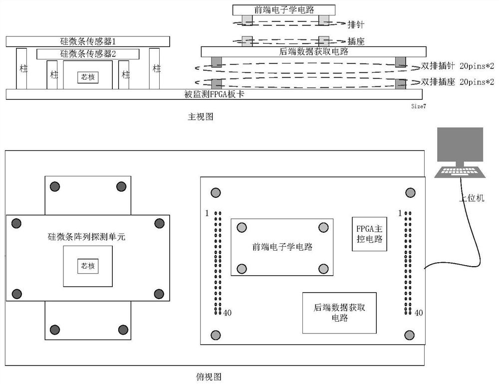
[0039] Such as figure 1 As shown, the present invention proposes a silicon microstrip detection system, including a silicon microstrip array detector, a front-end electronics unit, a back-end data acquisition unit, an FPGA main control unit, and a data processing unit set on a host computer.

[0040] 1. Silicon microstrip array detector

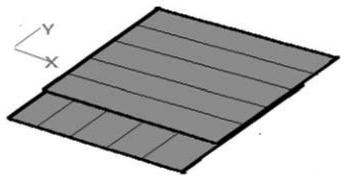
[0041] The silicon microstrip array detector consists of 2 silicon microstrip sensors, and each sensor has 5 detection units (10mm×10mm), such as figure 2 shown.

[0042] These two silicon micro-strip sensors form a 5×5 micro-strip array in a vertical and horizontal manner, and each micro-strip has a size of 2mm×2mm, and can output signals independently. The structure of the silicon microstrip array detector is as follows image 3 Shown: from top to bottom are silicon microstrip sensor 1 and silicon mi...


PUM


Abstract

The invention discloses a silicon micro-strip detection system. The silicon micro-strip detection system comprises a silicon micro-strip array detector, a front-end electronics unit, a rear-end data acquisition unit, an FPGA main control unit and a data processing unit arranged on an upper computer, wherein the front-end electronics unit is used for converting a charge output signal generated by the silicon micro-strip array detector into a voltage signal, comparing a voltage value with a threshold value, outputting a trigger signal for data acquisition to the main control circuit if the voltage value exceeds the threshold value, and converting the voltage signal into a serial differential current signal; the rear-end data acquisition unit is used for converting the serial differential current signal into a digital quantity; the FPGA main control unit is used for providing enable signals for the front-end electronics circuit and the rear-end data acquisition circuit after receiving trigger signals of data acquisition, reading data output by the rear-end data acquisition circuit and storing the data; and the data processing unit is used for receiving data of the silicon micro-strip array detector and determining the position and energy of spatial particles incident on the silicon micro-strip array detection unit.

Description


Claims


Application Information

Patent Timeline
Owner NAT SPACE SCI CENT CAS
Why Eureka
Try Eureka