Broadband steep cut-off wave-transparent structure based on frequency selective surface and antenna housing

A frequency-selective surface and wave-transparent structure technology, which is applied to antennas, antenna parts, radiation unit covers, etc., can solve the problem of narrow transition bands from suppression bands to transmission bands

Active Publication Date: 2021-04-13
AEROSPACE INST OF ADVANCED MATERIALS & PROCESSING TECH
View PDF10 Cites 0 Cited by
  • Summary
  • Abstract
  • Description
  • Claims
  • Application Information

AI Technical Summary

Problems solved by technology

[0003] The wave-transmitting structure based on the frequency selective surface has been related to the wave-transmitting performance of the C, S, X, and Ku bands. At present, there is no wide-band wave-transmission in the Ku-band, and the transition zone from the suppression band to the transmission band. Narrower, that is, wave-transparent structures based on frequency-selective surfaces that meet steep cut-off characteristics

Method used


Image

  • Broadband steep cut-off wave-transparent structure based on frequency selective surface and antenna housing
  • Broadband steep cut-off wave-transparent structure based on frequency selective surface and antenna housing
  • Broadband steep cut-off wave-transparent structure based on frequency selective surface and antenna housing

Examples


Embodiment Construction

[0024] It should be noted that, in the case of no conflict, the embodiments in the present application and the features in the embodiments can be combined with each other. The following will clearly and completely describe the technical solutions in the embodiments of the present invention with reference to the accompanying drawings in the embodiments of the present invention. Obviously, the described embodiments are only some, not all, embodiments of the present invention. The following description of at least one exemplary embodiment is merely illustrative in nature and in no way taken as limiting the invention, its application or uses. Based on the embodiments of the present invention, all other embodiments obtained by persons of ordinary skill in the art without creative efforts fall within the protection scope of the present invention.

[0025] It should be noted that the terminology used here is only for describing specific implementations, and is not intended to limit t...


PUM

PropertyMeasurementUnit
Thicknessaaaaaaaaaa

Abstract

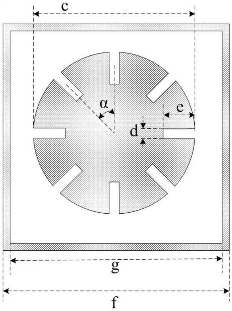
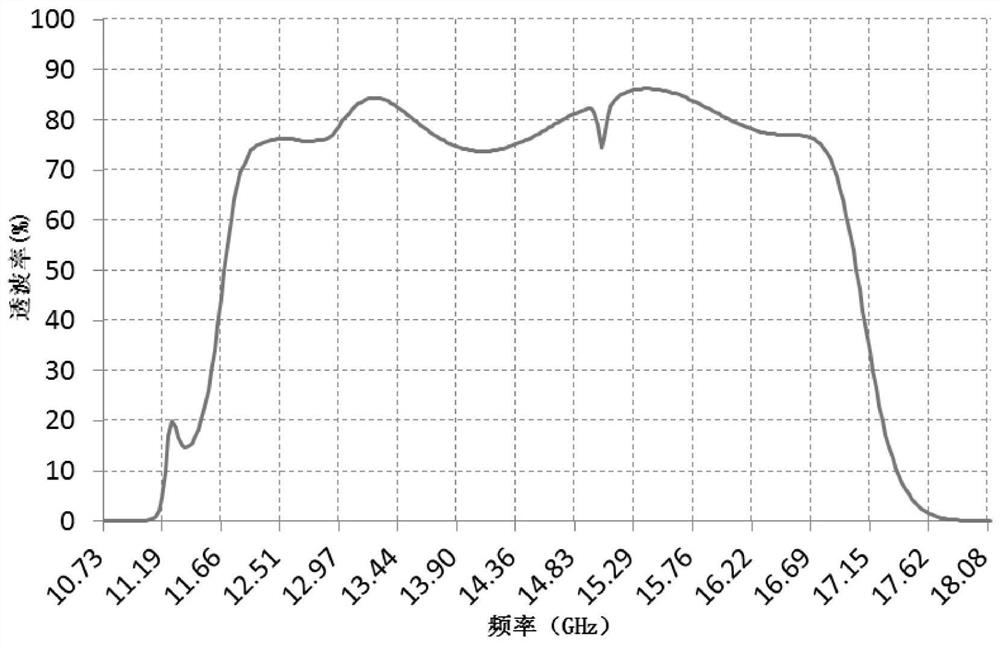
The invention provides a broadband steep cut-off wave-transparent structure based on a frequency selective surface and an antenna housing, and solves the problem that the high wave-transmitting characteristic and the steep cut-off characteristic of a passband window are difficult to meet in a Ku waveband broadband range. The wave-transparent structure comprises a first wave-transparent substructure, a second wave-transparent substructure and a third wave-transparent substructure which are sequentially arranged in the thickness direction of the wave-transparent structure, the first wave-transparent substructure and the second wave-transparent substructure are arranged at intervals to form a first foam layer, and the second wave-transparent substructure and the third wave-transparent substructure are arranged at intervals to form a second foam layer. Each of the first, second and third wave-transparent substructures consists of a first dielectric layer, a first frequency selection layer arranged on the first dielectric layer, a second dielectric layer, a second frequency selection layer arranged on the second dielectric layer, a third dielectric layer and a third frequency selection layer arranged on the third dielectric layer in sequence, and the first, second and third frequency selection layers adopt the same frequency selection surface structure. The gap type units are arranged periodically, and each gap type unit is composed of an annular structure ring and a patch structure which is located at the periphery of the outer edge of the inner center of the annular structure ring and provided with a plurality of grooves at intervals.

Description

technical field [0001] The invention provides a frequency-selective surface-based broadband steep cut-off wave-transmitting structure and a radome, which belong to the technical field of electromagnetic fields and microwaves. Background technique [0002] The frequency selective surface is a single-screen or multi-screen periodic array structure composed of a large number of passive resonant units. The frequency-selective surface unit structure can be divided into two types: patch-type unit structure and slot-type unit structure. The two types are complementary in pattern, and the frequency response characteristics of the two are opposite. The patch type unit structure is to paste some unconnected metal patterns on the dielectric board according to a certain period, and the slot type unit structure is to arrange some slit patterns according to a certain period on a complete metal layer. In addition to the effect of mechanical strength, dielectric loading can also affect the...

Claims


Application Information

Patent Timeline
IPC IPC(8): H01Q15/00H01Q1/42
CPCH01Q15/0026H01Q1/424
Inventor 丛琳张春波樊君徐向华阳开华杨帆张昊
Owner AEROSPACE INST OF ADVANCED MATERIALS & PROCESSING TECH
Why Eureka
Try Eureka