Shock absorption and heat dissipation power cabinet for power engineering

A technology of power engineering and power cabinets, which is applied in the field of shock absorption and heat dissipation power cabinets, can solve the problems of aggravated vibration effect, more and more vibration of the cabinet body, poor heat dissipation effect, etc., and achieve the effect of maintaining cleanliness and reducing friction

Pending Publication Date: 2021-04-13
GUANGDONG UNITED WATT POWER EQUIP CO LTD
View PDF6 Cites 12 Cited by
  • Summary
  • Abstract
  • Description
  • Claims
  • Application Information

AI Technical Summary

Problems solved by technology

[0004] The purpose of the present invention is: in order to solve the problem that the traditional power cabinet is not equipped with any cleaning structure inside, resulting in a large amount of dust or dirt easily adhering to the heat dissipation net of the power cabinet during long-term use, resulting in a decline in the cleanliness of the power cabinet. It will block the heat dissipation holes and affect the heat dissipation. At the same time, there is no other heat dissipation structure installed in the power cabinet, and the heat dissipation effect is not good. Only shock absorption springs are installed in the power cabinet for shock absorption, but during the shock absorption process, the cabinet body is prone to appear. The situation of more and more vibrations not only cannot solve the vibration problem, but also aggravates the problem of the vibration effect, and the proposed shock absorption and heat dissipation power cabinet for power engineering

Method used


Image

  • Shock absorption and heat dissipation power cabinet for power engineering
  • Shock absorption and heat dissipation power cabinet for power engineering
  • Shock absorption and heat dissipation power cabinet for power engineering

Examples


Embodiment Construction

[0045] The following will clearly and completely describe the technical solutions in the embodiments of the present invention with reference to the accompanying drawings in the embodiments of the present invention. Obviously, the described embodiments are only some of the embodiments of the present invention, not all of them. Based on the embodiments of the present invention, all other embodiments obtained by persons of ordinary skill in the art without creative efforts fall within the protection scope of the present invention.

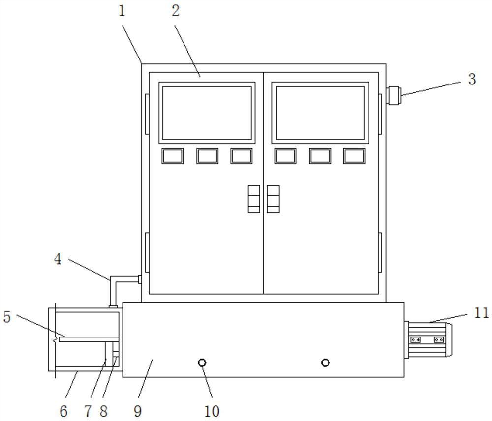
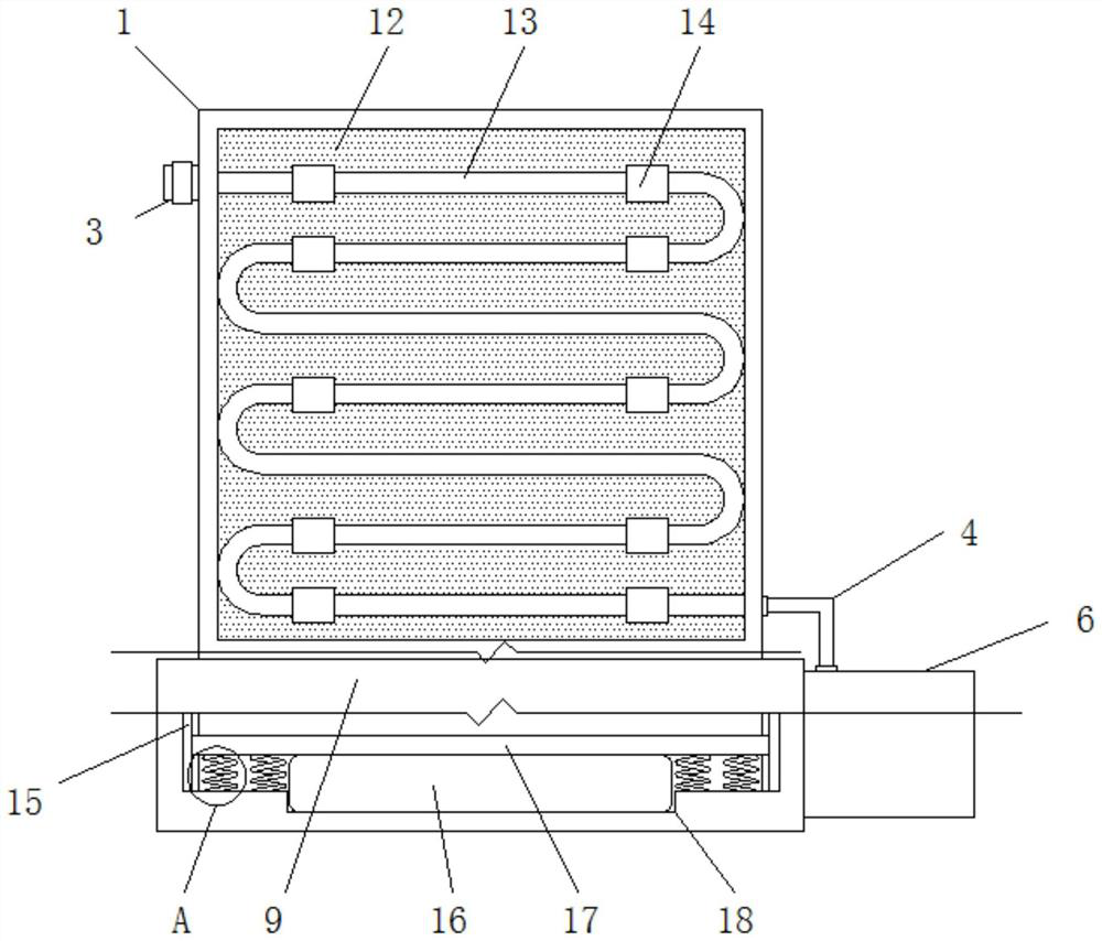
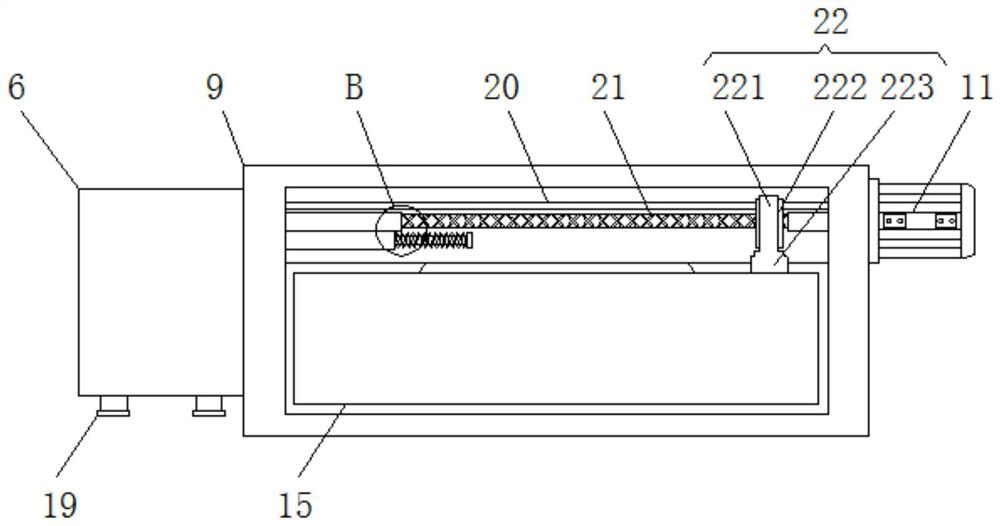
[0046] see Figure 1-8 , the present invention provides a technical solution: a shock-absorbing and heat-dissipating power cabinet for electric power engineering, including a cabinet body 1, a coolant tank 6, a liquid replacement assembly 8, a machine base 9, a reciprocating screw 21, a cleaning assembly 22 and a shock-absorbing Spring 30, the outside of the base 9 is hingedly equipped with a cabinet door 2, the outer walls of both sides of the base 9...


PUM


Abstract

The invention discloses a shock absorption and heat dissipation power cabinet for power engineering, which belongs to the technical field of power cabinets, and comprises a cabinet body, a cooling liquid box, a liquid changing assembly, a machine base, a reciprocating screw rod, a cleaning assembly and a shock absorption spring, wherein a cabinet door is hinged to the exterior of the machine base through a hinge, and a driving motor and the cooling liquid box are fixedly installed on the outer walls of the two sides of the machine base respectively; an inner cabinet base is fixedly installed in the machine base. The cooling liquid pipe is mounted inside, and the cleaning assembly capable of reciprocating is mounted in the power cabinet base, so that when the power cabinet is used in ordinary times, the driving motor can be started and can drive the mounting shaft to rotate, thereby driving the reciprocating lead screw to rotate and driving the cleaning assembly to move; the cleaning brush of the cleaning assembly can effectively clean the heat dissipation opening of the power cabinet, the cleanliness of the power cabinet is kept, meanwhile, the heat dissipation opening can be effectively prevented from being blocked by dust or dirt, and the heat dissipation effect of the power cabinet is guaranteed.

Description

technical field [0001] The invention belongs to the technical field of power cabinets, and in particular relates to shock-absorbing and heat-dissipating power cabinets used in electric power engineering. Background technique [0002] In the power industry, the power cabinet is one of the most important and basic structures. The power cabinet is divided into power power cabinets, lighting power cabinets, and metering cabinets. It is the final equipment of the power distribution system. The power cabinet is a general term for the motor control center. The power cabinet is used in the occasions where the load is relatively scattered and there are few circuits; the motor control center is used in the occasions where the load is concentrated and there are many circuits. They distribute the electric energy of a certain circuit of the upper-level power distribution equipment to the nearest load. This level of equipment shall provide protection, monitoring and control of the load....

Claims


Application Information

Patent Timeline
Patent Type & Authority Applications(China)
IPC IPC(8): H02B1/56H02B1/28H02B1/30H02B1/54
CPCH02B1/565H02B1/28H02B1/30H02B1/303H02B1/306H02B1/54
Inventor 胡鹏许岳金
Owner GUANGDONG UNITED WATT POWER EQUIP CO LTD
Why Eureka
Try Eureka