Wood deburring and mortise and tenon hole forming device

A technology for deburring and deburring mechanisms, which is applied in the direction of grinding drive devices, grinding machines, fixed drilling machines, etc. It can solve the problems that cannot be spliced ​​with mortise and tenon structures, and achieve the effect of saving manpower and consistent moving distance

Active Publication Date: 2021-04-16
湖南春江木业有限公司
View PDF15 Cites 0 Cited by
  • Summary
  • Abstract
  • Description
  • Claims
  • Application Information

AI Technical Summary

Problems solved by technology

[0004] In order to overcome the shortcomings that some parts of the wood are easy to be unpolished during manual grinding, and the manual opening is not vertical and cannot be used for the splicing of mortise and tenon structures. Straight, can be directly used in tenon and tenon structure, and can remove the wood surface burr wood deburring tenon and tenon hole device

Method used


Image

  • Wood deburring and mortise and tenon hole forming device
  • Wood deburring and mortise and tenon hole forming device
  • Wood deburring and mortise and tenon hole forming device

Examples


Embodiment 1

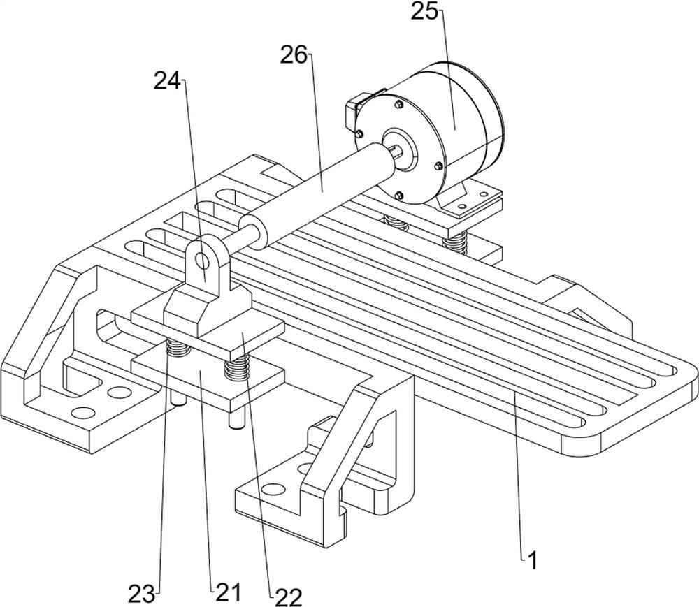
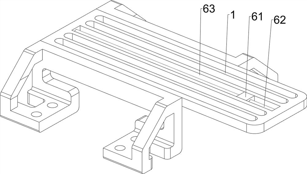
[0058] A wood deburring device for opening tenon and tenon holes, such as figure 1 As shown, it includes a mounting frame 1 , a deburring mechanism 2 and a punching mechanism 3 , the top of the mounting frame 1 is provided with a deburring mechanism 2 , and the deburring mechanism 2 is provided with a punching mechanism 3 .

[0059] Such as figure 2 As shown, the deburring mechanism 2 includes a first mounting plate 21, a second mounting plate 22, a first spring 23, a mounting block 24, a motor 25 and a grinding wheel 26, and the middle part of the front and rear sides of the mounting frame 1 is provided with a first mounting plate 21. A second mounting plate 22 is slidingly provided on the first mounting plate 21. Two first springs 23 are connected between the bottom of the second mounting plate 22 on the front and rear sides and the first mounting plate 21. Two mounting plate 22 tops are provided with mounting block 24, and mounting block 24 upper side rotations are provid...

Embodiment 2

[0063] On the basis of Example 1, such as Figure 4 As shown, a clamping mechanism 4 is also included, and the clamping mechanism 4 includes a placement plate 42, a first clamping plate 43, a second clamping plate 44, a first guide rod 45, a second spring 46 and a screw rod 47, and the mounting bracket 1 The top is placed with a placement plate 42, the left and right sides of the top of the placement plate 42 are provided with a first clamp 43, the first clamp 43 is provided with a first guide rod 45 on both sides, the first guide rod 45 on the left and right sides A second clamping plate 44 is slidably connected between them, two second springs 46 are connected between the second clamping plate 44 and the first clamping plate 43 , and a screw rod 47 is screwed on the right first clamping plate 43 .

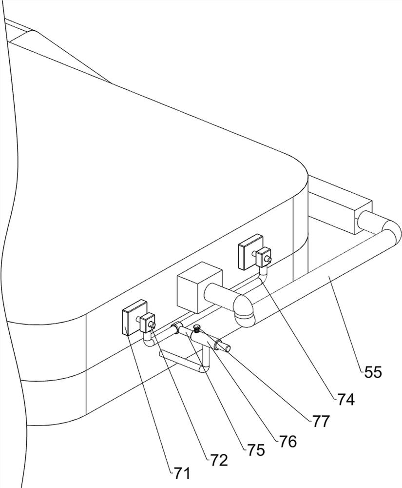
[0064] Such as Figure 5 As shown, a driving mechanism 5 is also included, and the driving mechanism 5 includes a guide rail 51, a second rack 52, a second guide rod 53, a secon...


PUM


Abstract

The invention relates to a mortise and tenon hole forming device, in particular to a wood deburring and mortise and tenon hole forming device. According to the wood deburring and mortise and tenon hole forming device, a formed hole is vertical and can be directly used for a mortise and tenon structure, and burrs on the surface of wood can be removed. According to the technical scheme, the wood deburring and mortise and tenon hole forming device comprises a mounting frame, wherein a deburring mechanism is arranged at the top of the mounting frame; and a punching mechanism arranged on the deburring mechanism. Wood with different thicknesses can be ground through the arranged deburring mechanism. Through the arrangement of the punching mechanism, a worker only needs to intermittently push wood to move, and then punching work can be completed on the wood. The wood can be clamped through a arranged clamping mechanism, and the position of the wood is prevented from deviating during punching work.

Description

technical field [0001] The invention relates to a device for opening mortise and tenon holes, in particular to a device for opening mortise and tenon holes for deburring wood. Background technique [0002] When the wood needs to be spliced ​​together without affecting its overall structure, the mortise and tenon structure is usually used, so it needs to be drilled. At present, it is manually drilled with drilling tools, but when doing this work manually , the hand-held drilling tool is not stable, so that the opened hole is not vertical, and cannot be used for the splicing of the mortise and tenon structure. In order to ensure that the gap between the wood is not large and make it fit closely, it needs to be deburred Work, manually use sandpaper to stick to the surface of the wood, and then press the sandpaper firmly and move it at the same time to remove the burrs. This method has a slower working efficiency, and some parts of the wood are likely to be unsanded during manua...

Claims


Application Information

Patent Timeline
Patent Type & Authority Applications(China)
IPC IPC(8): B24B9/00B24B9/18B24B7/02B24B7/28B24B41/06B24B47/20B27C3/02
CPCY02P70/10
Inventor 郭文靖
Owner 湖南春江木业有限公司
Why Eureka
Try Eureka