Damping device for new energy automobile battery

A technology for new energy vehicles and shock absorbers, applied in battery/fuel cell control devices, electric power devices, electric vehicles, etc., can solve problems such as inconvenient battery installation, battery water short-circuit, and battery damage.

Inactive Publication Date: 2021-04-16
林玉珍
View PDF6 Cites 4 Cited by
  • Summary
  • Abstract
  • Description
  • Claims
  • Application Information

AI Technical Summary

Problems solved by technology

[0004] In the above-mentioned 202010497159.4 patent, although heat can achieve the shock absorption effect on the new energy vehicle battery, it can only play a shock absorption effect on the installation of a single battery. Since the battery of the new energy vehicle has multiple sets, when multiple sets of batteries are installed After installation, the batteries will collide with each other when they vibrate, resulting in damage to the batteries, and the vibration of the batteries is mechanical energy, which will lead to energy waste if they are discarded. Moreover, when multiple batteries are installed, the batteries are close to each other, which will affect the heat dissipation performance of the batteries. The battery is burned out due to overheating, and the battery is fixed by the elastic force of the spring. When installing, it is necessary to overcome the elastic force of the spring by hand, which makes the installation of the battery inconvenient. Because the elastic force of the spring does not fix the battery firmly, the new energy vehicle is running. During the process, the battery will shake from side to side, and then the wire will be pulled and broken, and the waterproof effect on the battery cannot be achieved, resulting in the short circuit of the battery entering the water when the new energy vehicle is driving through water.

Method used


Image

  • Damping device for new energy automobile battery
  • Damping device for new energy automobile battery
  • Damping device for new energy automobile battery

Examples


Embodiment 1

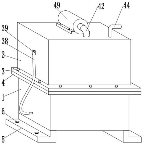
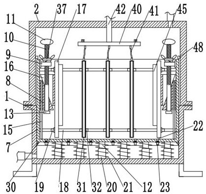
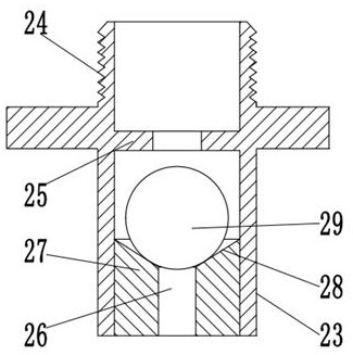
[0043]A shock-absorbing device for a battery of a new energy vehicle, comprising a lower casing 1, and a placement box 7 is slidably connected to the inside of the lower casing 1, the battery is installed inside the placement box 7, and the placement box 7 can be placed in the lower casing when the battery is vibrated. 1 slides inside, the bottom outer wall of the storage box 7 is provided with a sealing body 30, the sealing body 30 is made of fluorine rubber material, so that when the storage box 7 slides inside the lower casing 1, the air inside the lower casing 1 can be discharged , the outer wall of the bottom of the storage box 7 is welded with evenly distributed guide posts 12, and the inner wall of the bottom of the lower housing 1 is welded with evenly distributed guide sleeves 20. There is a spring 21, and the spring 21 is used to buffer the vibration of the battery. There are two extrusion plates 17 inside the storage box 7, and the two extrusion plates 17 are used to...


PUM


Abstract

The invention relates to the field of new energy vehicles, and aims to provide a damping device for a new energy vehicle battery, which comprises a lower shell, a placement box is slidably connected to the interior of the lower shell, a sealing body is arranged on the outer wall of the bottom of the placement box, and uniformly distributed guide columns are welded to the outer wall of the bottom of the placement box; guide sleeves which are evenly distributed are welded to the inner wall of the bottom of the lower shell, the guide columns are inserted into the guide sleeves in a sliding mode, the guide sleeves are sleeved with springs, two extrusion plates are arranged in the containing box, protective layers are bonded to the outer walls of one sides of the two extrusion plates, and air guide holes which are evenly distributed are formed in the protective layers. According to the damping device for the new energy automobile battery, the springs are used for achieving the damping effect on the new energy automobile battery in the storage box in the up-down direction, the protective layer is used for achieving the damping effect on the new energy automobile battery in the left-right direction, the multiple sets of batteries have the buffering damping effect through the buffering particles, and therefore the good damping effect on the batteries is achieved.

Description

technical field [0001] The invention relates to the field of new energy vehicles, in particular to a shock absorbing device for a new energy vehicle battery. Background technique [0002] With the advancement of science and technology and serious environmental pollution, people began to seek less polluting means of transportation, and new energy vehicles were also born. In new energy vehicles, batteries are the power heart of new energy vehicles, and its related technologies Particularly important. [0003] Chinese Patent No. 202010497159.4 discloses a shock absorber for new energy vehicles, which includes a first horizontal plate and a first concave plate. An elastic device is installed on the upper surface of a horizontal plate. The shock absorbing device for new energy vehicles can weaken and isolate the impact of vehicle vibration on the battery pack through the mutual cooperation between the battery pack, the first horizontal plate, the second horizontal plate, the to...

Claims


Application Information

Patent Timeline
IPC IPC(8): B60K1/00B60K1/04B60L50/60B60L58/26F16F15/02F16F15/067
CPCY02T10/70
Inventor 林玉珍
Owner 林玉珍
Why Eureka
Try Eureka