Wine jar mud sealing equipment for wine brewing
A mud sealing and equipment technology, applied in packaging sealing/fastening, conveyor objects, external support, etc., to solve problems such as manual smearing of sealing mud
- Summary
- Abstract
- Description
- Claims
- Application Information
AI Technical Summary
Problems solved by technology
Method used
Image
Examples
Embodiment 1
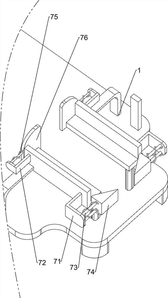
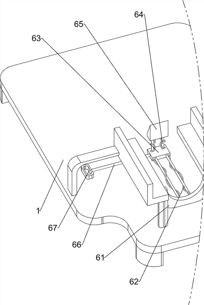
[0067]A kind of mud sealing equipment for wine jars, such as figure 1 As shown, it includes a base 1, a shaping mechanism 2 and a compacting mechanism 3. The front side of the base 1 is provided with a shaping mechanism 2, and the shaping mechanism 2 is provided with a compacting mechanism 3.
[0068] When winemakers need to mud seal wine jars, they can use this kind of mud sealing equipment. First, people place the wine jars to be mud sealed on the front side of the base 1 under the shaping mechanism 2, and then open the shaping mechanism 2 to shape the wine jars. The mechanism 2 drives the compacting mechanism 3 to move up and down. When the shaping mechanism 2 moves down to the mouth of the wine jar, the shaping mechanism 2 shapes the soil on the mouth of the wine jar, and the compacting mechanism 3 continues to move down, and the top of the shaping mechanism 2 The unshaped soil is compacted and sealed, so that the mud sealing operation to the wine jar can be completed. Aft...
Embodiment 2
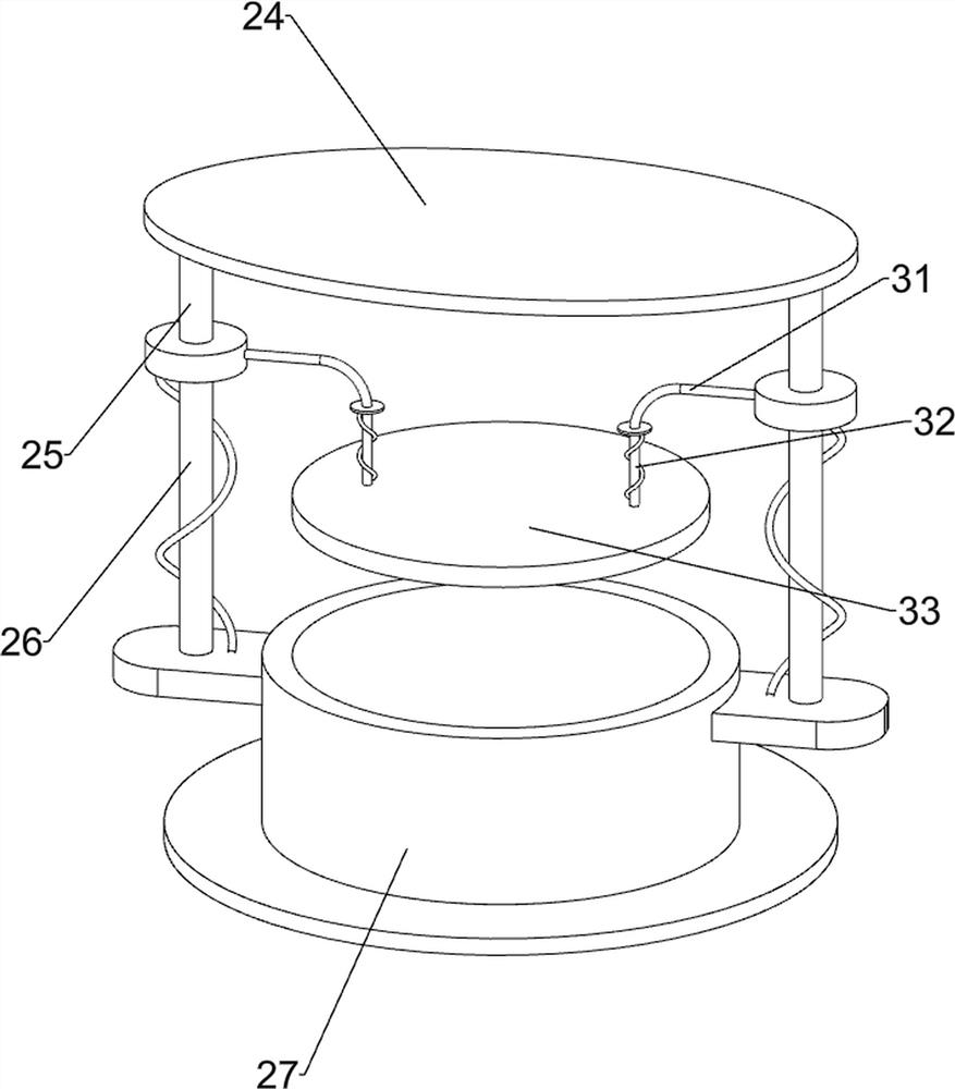
[0070] On the basis of Example 1, such as figure 2 and image 3 As shown, the sizing mechanism 2 includes a first support frame 21, a support plate 22, a cylinder 23, an elliptical push plate 24, a first connecting rod 25, a first telescopic assembly 26 and a sizing plate 27. The first support frame 21 is arranged on the top of the first support frame 21, and a support plate 22 is connected between the tops of the two first support frames 21. A cylinder 23 is installed on the support plate 22, and an elliptical push plate 24 is arranged at the bottom of the telescopic rod of the cylinder 23. The elliptical push plate The left and right sides of the bottom of 24 are provided with first connecting rods 25, and the bottom ends of the first connecting rods 25 are provided with first telescopic assemblies 26, and a shaping plate 27 is connected between the bottom ends of the two first telescopic assemblies 26.
[0071] Open the cylinder 23, the extension of the telescopic rod of ...
Embodiment 3
[0075] On the basis of Example 2, such as Figure 4-7 As shown, it also includes a positioning clamping mechanism 4, and the positioning clamping mechanism 4 includes a third connecting rod 41, a first wedge block 42, a third telescopic assembly 43 and an arc positioning plate 44, and both left and right sides of the shaping plate 27 are The third connecting rod 41 is symmetrically arranged, the bottom end of the third connecting rod 41 is provided with a first wedge-shaped block 42, and the left and right sides of the lower part of the first support frame 21 are provided with a third telescopic assembly 43, and inside the two third telescopic assemblies 43 The end is symmetrically provided with an arc-shaped positioning plate 44 , and the arc-shaped positioning plate 44 cooperates with the first wedge-shaped block 42 .
[0076] The shaping plate 27 moves up and down to drive the third connecting rod 41 and the first wedge-shaped block 42 to move up and down. When the first we...
PUM
 Abstract
Description
Claims
Application Information
 - R&D
- Intellectual Property
- Life Sciences
- Materials
- Tech Scout
- Unparalleled Data Quality
- Higher Quality Content
- 60% Fewer Hallucinations
Browse by: Latest US Patents, China's latest patents, Technical Efficacy Thesaurus, Application Domain, Technology Topic, Popular Technical Reports.
© 2025 PatSnap. All rights reserved.Legal|Privacy policy|Modern Slavery Act Transparency Statement|Sitemap|About US| Contact US: help@patsnap.com


