Sectional type traction device for flat knitting machine and traction unit control method

A technology of flat knitting machine and pulling device, which is applied in the direction of weft knitting, knitting, textile and paper making, and can solve the problems of high manufacturing cost, complex structure of transmission mechanism, poor applicability, etc.

Active Publication Date: 2021-04-16
冯加林 +2
View PDF5 Cites 3 Cited by
  • Summary
  • Abstract
  • Description
  • Claims
  • Application Information

AI Technical Summary

Problems solved by technology

This type of pulling device is suitable for pulling the whole braided fabric. If it is necessary to pull the braided fabric partially, even if the segmented roller is used, the pulling effect is very poor, and it is easy to form waste products. If it is a complex weaving, such as a full-molded Weaving, let alone achieve the required pulling effect
[0003] At present, there are pulling devices that use pull

Method used


Image

  • Sectional type traction device for flat knitting machine and traction unit control method
  • Sectional type traction device for flat knitting machine and traction unit control method
  • Sectional type traction device for flat knitting machine and traction unit control method

Examples


Embodiment 1

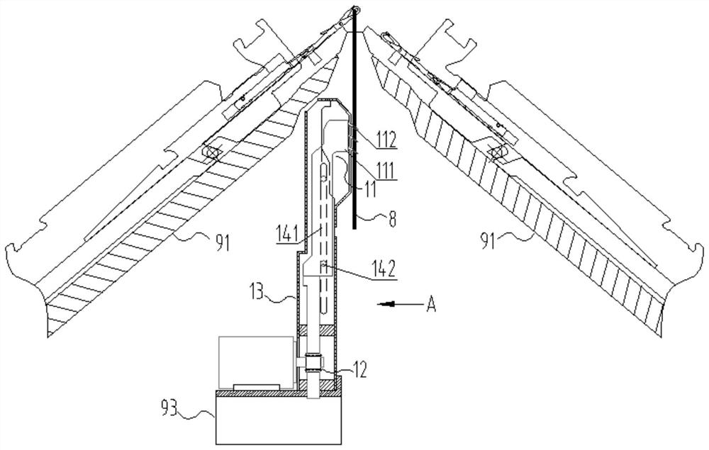
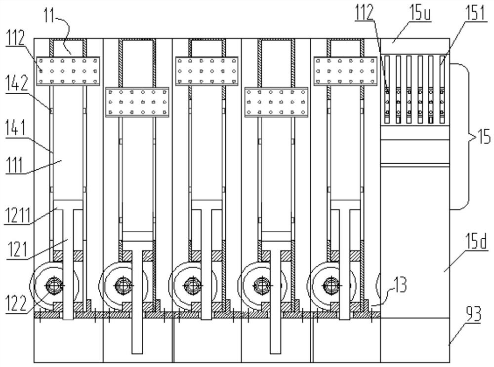
[0046] Such as Figure 1-3 The pulling device is arranged below the needle plate 91 of the flat knitting machine and on one side of the path of the braided fabric 8. The pulling device includes six horizontally arranged pulling mechanisms 1, and each pulling mechanism 1 is mainly composed of a fixed seat 13, a pulling mechanism The pull unit 11 and the drive unit 12 are composed. The pulling unit 11 is provided with a pulling hook 112 for hooking the braided fabric, the driving unit 12 is fixedly arranged on the fixed upper seat 13, and a driving end 1211 which can move up and down is provided on it, and the pulling unit 11 passes through a relatively movable The guide structure formed by the guide piece and the guide groove can be slidably arranged on the fixed seat 13, and the pulling unit 11 moves upward under the action of the contact driving of the driving end 1211 of the driving unit 12, and the pulling unit 11 moves upward when the driving end moves down. It will move ...

Embodiment 2

[0055] Several pulling mechanisms 1 that make up the pulling device of this embodiment are arranged on as figure 1 The braided fabric 8 under the needle plate 91 of the shown flat knitting machine is on one side or both sides of the path, and similarly, several pulling mechanisms 1 on the one side or both sides are fixed side by side on the corresponding side of the transverse base. Seat 93.

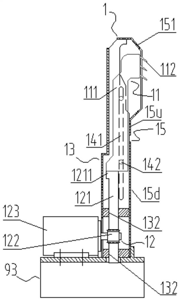
[0056] Such as Figure 4 , same as above-mentioned embodiment 1, its pulling mechanism 1 comprises fixed seat 13, pulling unit 11, drive unit 12 and shield plate 15, is provided with the shield plate 15 of slotted hole 151 and is arranged on fixed seat 13 corresponding to On one side of the braid, the pulling unit 11 is slidably arranged on the fixing seat 13 through a guide structure formed by a relatively movable guide piece and a guide groove. In this embodiment, guide grooves are provided on both sides (or one side) of the pulling unit 11. The guide grooves on each side are compose...

Embodiment 3

[0060] Figure 6 , a number of pulling mechanisms 1 that make up the pulling device of this embodiment are arranged as figure 1 The braided fabric 8 under the needle plate 91 of the shown flat knitting machine is on one side or both sides of the path, and similarly, several pulling mechanisms 1 on the one side or both sides are fixed side by side on the corresponding side of the transverse base. Seat 93.

[0061] Such as Figure 7 , 8 Similarly, the pulling mechanism 1 of this embodiment includes a fixing base 13 , a pulling unit 11 , a driving unit 12 , and a shield plate 15 disposed on one side of the fixing base and provided with a long slot 151 . The guide is arranged on the pulling unit 11, and a guide composed of two cylindrical pins 142 arranged up and down is provided on both sides (or one side) of the pulling unit; the guide groove 141 is a straight groove connected vertically and The straight inclined combination groove formed by the inclined groove at the upper ...


PUM


Abstract

The invention relates to a sectional type traction device for a flat knitting machine and a traction unit control method. Each traction mechanism comprises a fixed seat, a traction unit which is provided with a traction hook and is arranged on the fixed seat in a sliding manner, and a driving unit which is provided with a driving end capable of moving up and down and drives the traction unit to move upwards under the contact action of the driving end; the traction unit control method comprises the steps that a sensor is arranged on the traction unit or the driving unit, the sensor generates a detection signal when the driving end is close to or makes contact with the traction unit, a distance is generated between the traction unit and the driving end when the traction unit hooks a braided fabric, the distance interrupts the detection signal, and the detection signal is generated to enable the driving end to move upwards; and the driving end stops or moves downwards or upwards due to interruption of the detection signal, movement of the driving end is controlled through generation and interruption of the detection signal, and therefore the traction action of the traction unit is controlled, a transmission mechanism is greatly simplified, installation and debugging are quite convenient, and the production cost is reduced.

Description

technical field [0001] The invention relates to the technical field of flat knitting machines, in particular to a driving method for a pulling device of a flat knitting machine and a driving end of a driving unit. Background technique [0002] In order to prevent the coils from floating up during the weaving process, the flat knitting machine needs to pull the braided fabric downward through a pulling device. At present, a roller device is mainly used, and the braided fabric is clamped and pulled down by rollers with opposite rotation directions. This kind of pulling device is suitable for pulling the whole braided fabric. If it is necessary to pull the braided fabric partially, even if the segmented roller is used, the pulling effect is very poor, and it is easy to form waste products. If it is a complex weaving, such as a fully formed Weaving, more can't reach required pulling effect. [0003] At present, there are pulling devices that use pulling rakes, and there are als...

Claims


Application Information

Patent Timeline
IPC IPC(8): D04B15/90D04B15/96D04B15/99
Inventor 冯加林冯天元巫友群
Owner 冯加林
Why Eureka
Try Eureka