High speed magnetic suspension permanent magnet motor without bearing

A permanent magnet motor and magnetic levitation technology, which is applied to synchronous motors with stationary armatures and rotating magnets, electrical components, and magnetic circuit stationary parts, etc., can solve the problems of increased axial length of motors, complex structures, and wear and tear. Achieve the effect of increasing stiffness and critical speed, improving running stability, and shortening axial dimensions

Inactive Publication Date: 2008-06-25
SHENYANG POLYTECHNIC UNIV
View PDF0 Cites 24 Cited by
  • Summary
  • Abstract
  • Description
  • Claims
  • Application Information

AI Technical Summary

Problems solved by technology

However, the speed of high-speed motors is as high as tens of thousands or even hundreds of thousands of revolutions per minute, and the peripheral speed can reach more than 200m / s. It is difficult for permanent magnets to withstand the huge tensile stress caused by high-speed rotating centrifugal force. Generally, they need to be made of non-magnetic high-strength alloy materials. The sheath protects the permanent magnet
At the same time, traditional mechanical bearings used in high-speed motors will be worn out quickly, and non-mechanical contact bearings are required
Magnetic suspension bearings are more suitable for high-speed motors, but their structure is similar to that of a motor. Installing magnetic suspension bearings at both ends of a high-speed motor not only has a complex structure, but also greatly increases the axial length of the motor, thereby reducing the stiffness and criticality of the motor rotor. speed, which is not conducive to the stable operation of high-speed motors

Method used


Image

  • High speed magnetic suspension permanent magnet motor without bearing
  • High speed magnetic suspension permanent magnet motor without bearing

Examples


Embodiment Construction

[0019] The motor of the present invention will be further described below in conjunction with the accompanying drawings.

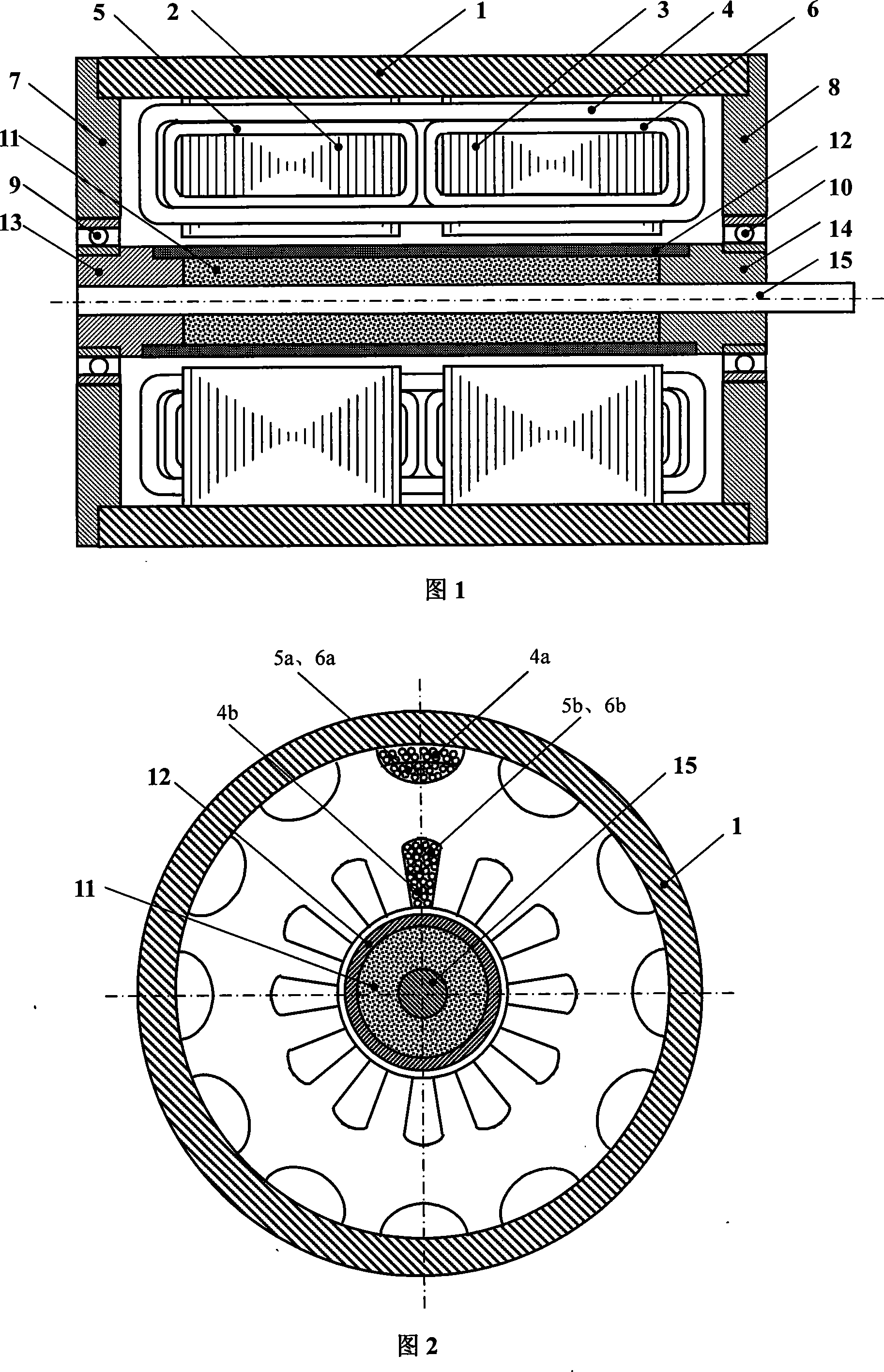
[0020] Fig. 1 is a schematic diagram of an axial section of a bearingless high-speed permanent magnet motor of the present invention, and Fig. 2 is a schematic diagram of a radial section of a bearingless high-speed permanent magnet motor of the present invention. Among them, 1 is the motor casing, which is used to fix the stator core and the left and right end covers of the motor; 2 is the left stator core; 3 is the right stator core; 4 is the 2-pole ring winding structure torque winding for generating electromagnetic torque , the lower side and the upper side are respectively placed in the radially inner and outer slots of the stator core; 5 is the left suspension force winding of the 4-pole ring structure, which is used to generate the left suspension force of the motor rotor, and the lower and upper coil sides are respectively placed In the radially in...


PUM


Abstract

The invention relates to a high-speed magnetic-suspension bearing-free permanent-magnetic machine, which comprises a shell, a stator core, a stator winding, a permanent-magnetic rotor, a rotating shaft, a left terminal cover, a right terminal cover, a left standby bearing and a right standby bearing. The stator core is divided into a right section and a left section and is provided with a groove that is used for holding the stator winding on the radial inner side and the radial outer side. The stator winding consists of a set of double-pole torque windings that are used for producing the electromagnetic torque and two sets of four-pole magnetic-suspension windings that are used for producing the rotor suspension force. The permanent-magnetic rotor consists of a permanent-magnet of a radial magnet-charging integral structure, a high-strength magnetic-conductive sheath and a fastening piece. The standby bearings are used for supporting the rotor when the high-speed motor is not powered on. The invention integrates the magnetic-suspension bearing and the permanent-magnetic machine, so that the stator and the rotor of the machine not only can produce the electromagnetic torque that drives the rotation of the motor, but also can produce the magnetic-suspension force that supports the weight of the rotor, thereby simplifying the structure of the machine, shortening the axial length of the machine, increasing the stiffness and the critical rotating speed of the rotor of the high-speed machine, and improving the stability of the operation.

Description

technical field [0001] The invention belongs to a motor, in particular to a high-speed magnetic suspension bearingless permanent magnet motor. The motor adopts a rotor with an integral structure of permanent magnets and a magnetically permeable sheath. The stator has a 2-pole torque winding and a 4-pole suspension force winding. The rotor is supported by the suspension force generated by the motor itself, without bearings, and is especially suitable for use as high-speed motor use. Background technique [0002] Due to the high speed and high power density of high-speed motors, its geometric size is much smaller than that of low- and medium-speed motors with the same output power, which can effectively save materials; it is directly connected with the prime mover or load, eliminating the need for mechanical transmission devices, thus reducing noise and Improve driveline efficiency. The application fields of high-speed motors are becoming more and more extensive, such as pro...

Claims


Application Information

Patent Timeline
Patent Type & Authority Applications(China)
IPC IPC(8): H02K1/27H02K1/12H02K3/04H02K21/12H02N15/00
Inventor 王凤翔邢军强张凤阁宗鸣王天煜孔晓光王大鹏
Owner SHENYANG POLYTECHNIC UNIV
Why Eureka
Try Eureka