Flowmeter with middle through-hole movable throttling element connected with elastic membranes or bellows

A technology of throttling elements and elastic diaphragms, which is applied to the volume/mass flow generated by mechanical effects, and the detection of fluid flow by measuring differential pressure. It can solve the problems of complex manufacturing and debugging of flowmeters, and affect measurement accuracy. Simple, cost-effective, high precision, and long service life

Inactive Publication Date: 2012-02-15
王可崇
View PDF4 Cites 25 Cited by
  • Summary
  • Abstract
  • Description
  • Claims
  • Application Information

AI Technical Summary

Problems solved by technology

In addition, the dynamic throttling element in the flowmeter is supported by a pair of moving pairs. The friction of the moving pairs not only affects the measurement accuracy, but also complicates the manufacture and debugging of the flowmeter.

Method used


Image

  • Flowmeter with middle through-hole movable throttling element connected with elastic membranes or bellows
  • Flowmeter with middle through-hole movable throttling element connected with elastic membranes or bellows
  • Flowmeter with middle through-hole movable throttling element connected with elastic membranes or bellows

Examples


Embodiment 1

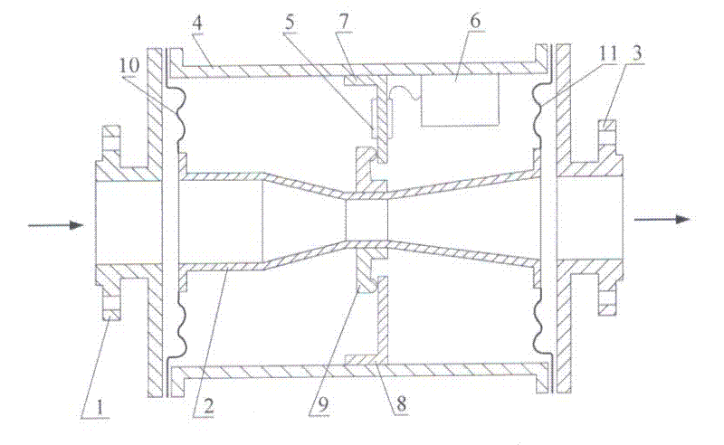
[0015] exist figure 1 In the embodiment, use two annular corrugated elastic membranes 10,11 with edge corrugations, the inner edges of the annular front elastic membrane 10 and the rear elastic membrane 11 are connected with the entrance of the Venturi tube 2 respectively. The outer edge of the front elastic membrane 10 and the rear elastic membrane 11 are sealed and connected with the front end tube 1 and the rear end tube 3 respectively. The casing frame 4 is rigidly connected with the front end pipe 1 and the rear end pipe 3, so that the distance between the two end pipes can be fixed, and other components can be installed thereon. The detection cantilever beam 7 and the balance cantilever beam 8 are installed on the chassis frame 4, the detection cantilever beam 7 is affixed with the strain gauge 5, and the balance cantilever beam 8 is not affixed with the strain gauge, the purpose of setting the balance cantilever beam 8 is to balance the detection The additional moment ...

Embodiment 2

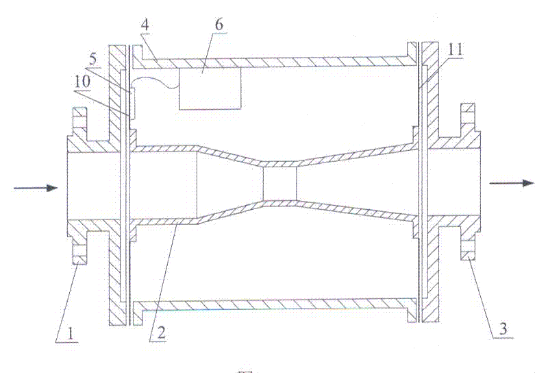
[0035] exist figure 2 In the implementation scheme, it can be seen that this example and figure 1 The embodiments are substantially the same in structure, with only the following two differences. First, in figure 2 In, two ring-shaped planar diaphragms 10, 11 are used instead of figure 1 There are two corrugated elastic diaphragms 10, 11 with corrugated edges. The inner edge of the flat front elastic diaphragm 10 is in sealing connection with the inlet end of the Venturi tube 2, and its outer edge is in sealing connection with the front end tube 1; The inner edge of the diaphragm 11 is sealingly connected with the outlet end of the Venturi tube 2, and its outer edge is sealingly connected with the rear end pipe 3; The dimple corresponding to the effective area of ​​the diaphragm allows the Venturi tube 2 to have a margin to move left and right along the axial direction. Second, the strain gauge 5 is pasted on the front plane diaphragm 10, and the detection cantilever bea...

Embodiment 3

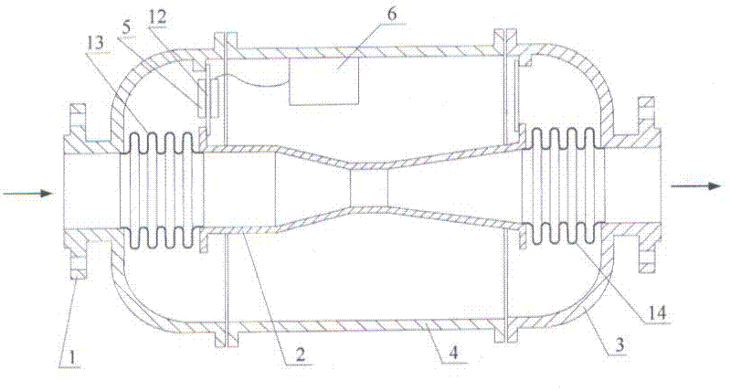
[0038] exist image 3 In the embodiment of the present invention, two U-shaped bellows 13, 14 are used, the front end of the front bellows 13 is in sealing connection with the front end pipe 1, and its rear end is in sealing connection with the inlet end of the Venturi tube 2; the front end of the back bellows 14 is in sealing connection with The outlet end of the Venturi tube 2 is in sealing connection, and its rear end is in sealing connection with the rear end pipe 3 . The weight of the Venturi tube 2 is supported by two elastic metal straps 12, and the strain gauge 5 is pasted on the metal straps 12. The metal sheet sling 12 is made of very thin elastic metal sheet, its stiffness coefficient along the pipeline axis is very small, and the rebound force generated by its deformation is also very small, so it can be considered that the thrust force on the Venturi tube 2 is F Balanced only by the rebound force of the two bellows. However, the deflection deformation of the met...


PUM


Abstract

The invention discloses a flowmeter with a middle through-hole movable throttling element connected with elastic membranes or a bellows, which belongs to the throttling flowmeter in the automatic detection technical field; the patent 'a middle through-hole movable throttling element flowmeter' depends on the thrust of the movable throttling element, and does not like a fixed throttling element which measures the flow according to the flow differential pressure, so a pressure pipe can be dispensed, the flowmeter is applicable to measuring small calibers and dirty liquids, the isolation, the pressure-bearing, the support and other functions of the flowmeter are all respectively realized through different components, and the integral structure is more complicated. The flowmeter adopts the elastic membranes or the bellows to be connected with the middle through-hole movable throttling element, the isolation, the pressure-bearing, the support and other functions are realized independently by the elastic membranes or the bellows, the integral structure of the flowmeter is greatly simplified, not only are all the advantages of the through-hole movable throttling element obtained, but also a plurality of performances are improved, and the invention makes the through-hole movable throttling element flowmeter which is a novel meter be more easily popularized and used.

Description

technical field [0001] The invention relates to an instrument for realizing flow detection in the technical field of automatic detection. Background technique [0002] At present, flow measurement using the throttling principle is still the most widely used. Most of the throttling devices used are fixed throttling elements, and a small part are dynamic throttling elements. Among flowmeters made using the throttling principle, differential pressure flowmeters use fixed throttling elements, while target flowmeters and rotameters use dynamic throttling elements. Commonly used fixed throttling elements include orifice plates, nozzles and venturi tubes. They have a long history of use, complete test data, and standardized products, so they are also called "standard throttling devices". In the measurement, the orifice plate, nozzle and Venturi tube are fixedly installed in the pipeline, and the fluid flows through the through hole in their middle; the dynamic throttling element o...

Claims


Application Information

Patent Timeline
Patent Type & Authority Applications(China)
IPC IPC(8): G01F1/36
Inventor 王可崇
Owner 王可崇
Why Eureka
Try Eureka