Turbulence structure for array impact jet cooling

A technology of impinging jets and arrays, which is applied in the field of spoiler structures, can solve problems such as large temperature gradients, offsets, and unreasonable impingement cooling systems, and achieve the effects of improving heat transfer efficiency, increasing heat transfer efficiency, and uniform temperature distribution

Pending Publication Date: 2018-12-11
SHENYANG AEROSPACE UNIVERSITY
View PDF7 Cites 4 Cited by
  • Summary
  • Abstract
  • Description
  • Claims
  • Application Information

AI Technical Summary

Problems solved by technology

[0006] (1) After the cooling air flow of the upstream impact hole hits the target plate, a certain amount of cross flow will be generated in the cooling channel, which will affect the downstream jet flow, causing the downstream jet flow to deviate, resulting in a decrease in the heat transfer efficiency of the target plate and Inhomogeneous cooling effect on the target surface
[0007] (2) After the spoiler element is installed on the target plate of the array jet cooling system, due to the unsatisfactory shape of the spoiler column, it cannot effectively hinder the development of cross flow, resulting in unsatisfactory improvement of the heat transfer effect, and the temperature of the target plate Although the gradient has improved, the temperature gradient is very large, and the heat transfer of the impacting target plate is still very uneven
[0008] (3) After the spoiler element is set on the target plate of the array jet cooling system, a large additional pressure loss is generated inside the impingement cooling system due to the existence of the spoiler column, which improves the overall heat transfer performance of the impingement cooling system Not as good as the increase in pressure loss, even if it produces better heat transfer performance, but it is not reasonable for the impingement cooling system

Method used


Image

  • Turbulence structure for array impact jet cooling
  • Turbulence structure for array impact jet cooling
  • Turbulence structure for array impact jet cooling

Examples


Embodiment Construction

[0031] The invention will be described in further detail below in conjunction with the accompanying drawings and specific examples, but the present invention is not limited to the following examples.

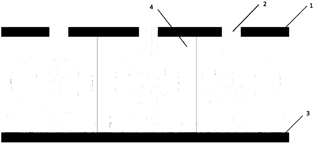
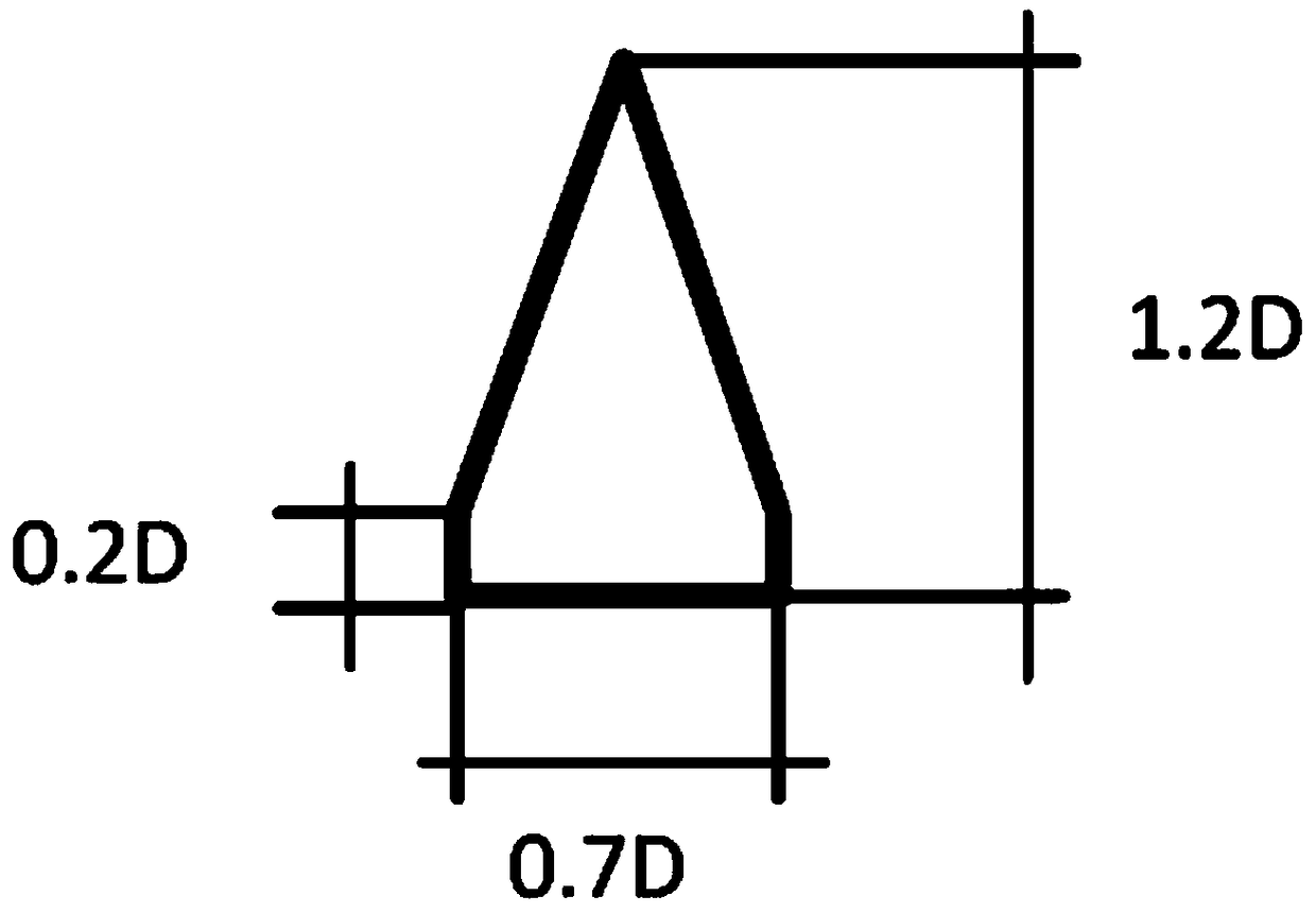
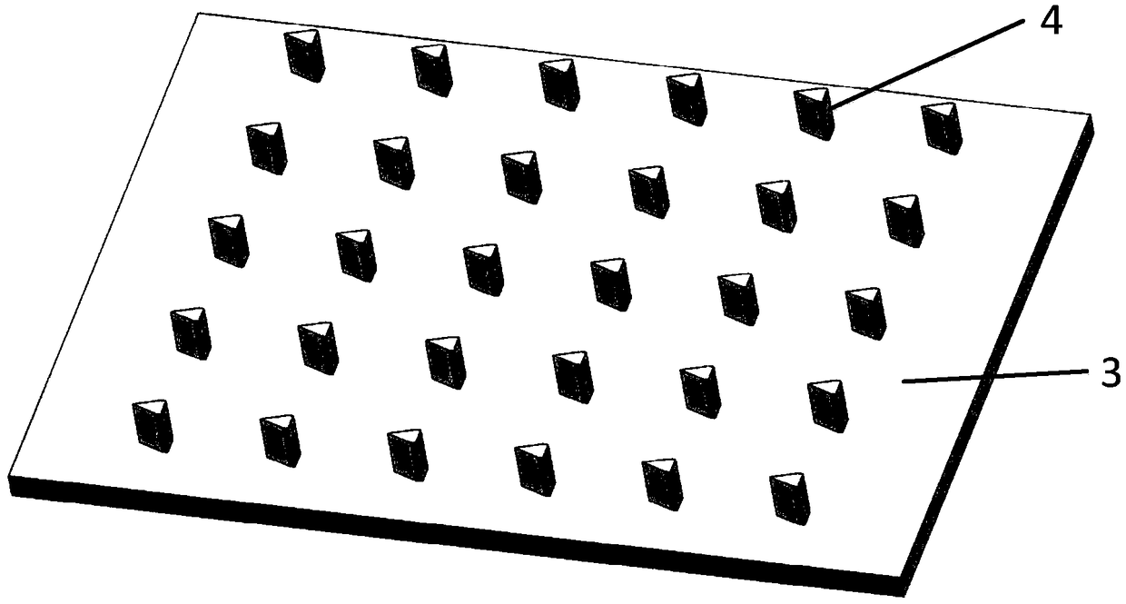
[0032] refer to figure 1 , a high-performance turbulence structure in array impingement jet cooling, comprising a jet orifice 1 and a jet target 3, the jet orifice 1 is provided with a plurality of impingement holes 2 arranged in an array; the jet orifice 1 is located in the The upper part of the jet target plate 3 is designed as a cavity between the two, and the spoiler column 4 is arranged on the jet target plate 3 , and the upper end of the spoiler column 4 is in contact with the jet orifice plate 1 . In this solution, the diameter of the impact hole 2 is set as D.

[0033] The spoiler column 4 is a column with a different pentagonal section, or a column with a nearly semi-elliptical dome-shaped section, or a column with a drop-shaped section.

[0034] As a scheme improveme...


PUM


Abstract

The invention belongs to the field of gas turbine and aero-engine high-temperature component cooling and other fields involved in array impact jet cooling, and particularly discloses a turbulence structure for array impact jet cooling. Three turbulence column structure designs are provided and include a jet target plate where special-pentagon-shaped turbulence column are distributed in an array mode, a jet target plate where domelike turbulence column are distributed in an array mode, and a jet target plate where drop-shaped turbulence column are distributed in an array mode. The turbulence structure has the advantages that the cooling efficiency is improved to a greatest extent with the smallest cooling air volume, the overall temperature gradient of the cooling wall is reduced, and heattransfer is more uniform and stable.

Description

Technical field: [0001] The invention belongs to the cooling of high-temperature components of gas turbines and aero-engines and other fields related to array impingement jet cooling, and specifically relates to a flow turbulence structure in array impingement jet cooling. Background technique: [0002] The gas turbine can provide powerful power mainly through its high-temperature and high-pressure gas. The initial temperature of the high-temperature gas determines the working efficiency of the gas turbine. In order to improve the efficiency of gas turbines, the temperature of the gas at the turbine inlet needs to be continuously increased. However, with the increase of gas temperature, the stability and life of the high-temperature components of the gas turbine are severely tested. At the same time, the development of materials cannot keep up with the performance requirements of gas turbines, so effective and advanced cooling technologies must be adopted to ensure the safe...

Claims


Application Information

Patent Timeline
Patent Type & Authority Applications(China)
IPC IPC(8): F01D25/12
CPCF01D25/12
Inventor 李润东郭曾嘉贺业光
Owner SHENYANG AEROSPACE UNIVERSITY
Why Eureka
Try Eureka