Combined curved-surface vortex generator-type round fin-tube heat exchanger

A generator and combined technology, applied in the direction of tubular elements, heat exchange equipment, lighting and heating equipment, etc., can solve the problems of large resistance loss, etc., and achieve the effects of improving heat exchange performance, good streamline, and inhibiting fluid separation

Active Publication Date: 2011-08-24
兰州金诺绿色能源动力科技有限责任公司
View PDF3 Cites 5 Cited by
  • Summary
  • Abstract
  • Description
  • Claims
  • Application Information

AI Technical Summary

Problems solved by technology

However, the flow linearity of the fluid flowing through the circular tube is worse than that of the flat tube, and the resistance loss is greater when the fluid flows near the stagnation point at the front end of the circular tube and through the wake area of ​​the circular tube.

Method used


Image

  • Combined curved-surface vortex generator-type round fin-tube heat exchanger
  • Combined curved-surface vortex generator-type round fin-tube heat exchanger
  • Combined curved-surface vortex generator-type round fin-tube heat exchanger

Examples


Embodiment Construction

[0015] Below in conjunction with accompanying drawing, the present invention is described in further detail:

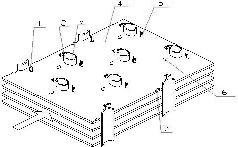
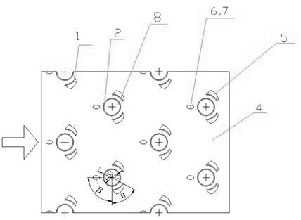
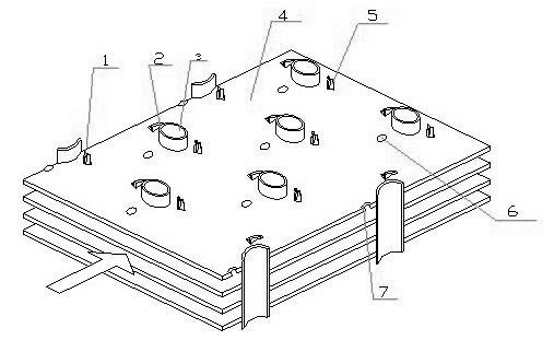
[0016] The present invention is a combined curved surface vortex generator type round tube fin heat exchanger, which includes round tubes 3 arranged along the gas flow direction and fins 4 sleeved on the round tubes 3, and the round tubes 3 can be forked rows Or arranged in a row, the fins 4 are provided with round holes 8 for the sleeved round tubes 3, and a pair of trapezoidal curved surface vortex generators 1 are punched out at the rear of each round hole 8, and a pair of trapezoidal curved surface vortex generators 1 are left on the fins 4. Small hole 5. The curved vortex generator 1 is distributed symmetrically up and down about the longitudinal centerline of the circular hole 8, the bottom edge of the curved vortex generator 1 connected to the fin 4 is an arc concentric with the circular hole 8, and the long bottom edge of the trapezoid connected to the bottom ...


PUM


Abstract

The invention relates to the technical field of heat exchangers, and discloses a combined curved-surface vortex generator-type round fin-tube heat exchanger, comprising round pipes arranged in the air flow direction and fins sheathed on the round pipes; the fins are provided with round holes sheathing the round pipes; a pair of trapezoid curved-surface vortex generators are punched at the rear part of each round hole; the bottom side of the curved-surface vortex generator and the round hole are respectively a concentric circle; a pair of trapezoid small holes are reserved on the fins; an elliptical convex hull is punched on the middle line at the front end of each round hole on the fin; and a concave pit is reserved on the backside of the fin. The liquid of the heat exchanger changes direction flowing the convex hull, thus the direct vertical washing to the round pipes by the liquid is reduced at the front part of the round pipe; the fluid is guided by the vortex generator to reach a round pipe tail stream area to inhibit the fluid at the rear side of the round pipe from separating; and the rear tail stream area of the round pipe is decreased, thus improving the heat exchanging performance on the contact surface of the fin and the tail stream area, and decreasing the loss of the flowing resistance in the tail stream area.

Description

technical field [0001] The invention relates to the technical field of heat exchangers, in particular to a combined curved surface vortex generator type round tube fin heat exchanger. Background technique [0002] Flat tube, tube and fin heat exchangers are commonly used equipment in industrial processes and refrigeration and air conditioning. In order to reduce energy consumption and reduce emissions, it is very meaningful to enhance the heat transfer performance of round tube fin heat exchangers. For the commonly used round tube fin heat exchanger, generally the liquid working medium flows in the tube, and the gas flows outside the tube. Since the specific heat of the gas is very small, the thermal resistance during the heat transfer process is mainly concentrated on the gas side. Installing fins on the air side to increase the heat transfer area and reduce the thermal resistance of the air side is an effective measure to improve heat transfer and has been widely used in ...

Claims


Application Information

Patent Timeline
Patent Type & Authority Applications(China)
IPC IPC(8): F28F1/32
Inventor 王良璧武祥常立民王良成张永恒林志敏董元信
Owner 兰州金诺绿色能源动力科技有限责任公司
Why Eureka
Try Eureka