Fiber rope pre-drawing device and pre-drawing method

A pre-drafting and rope technology, applied in the field of fiber ropes, can solve the problems of difficulty in accurate control of drafting force, complicated operation, contamination, etc., and achieves the effect of good practical value and broad application prospects.

Active Publication Date: 2022-02-18
SHANDONG ROPE TECH CO LTD +2
View PDF0 Cites 0 Cited by
  • Summary
  • Abstract
  • Description
  • Claims
  • Application Information

AI Technical Summary

Problems solved by technology

At present, the cyclic pre-drawing process of ropes is generally carried out on horizontal tension machines. For rope products with large lengths, such as deep-sea buoy mooring cables with a length of 500 meters or longer, they can only be used on sites with larger spans. The vehicle applies tension to the rope for pre-stretching. This pre-stretching method has the problems of complicated operation, difficulty in accurately controlling the drafting force, and the rope is easy to be brushed and stained during the pre-stretching process, and there are safety hazards in the stretching process.

Method used


Image

  • Fiber rope pre-drawing device and pre-drawing method
  • Fiber rope pre-drawing device and pre-drawing method
  • Fiber rope pre-drawing device and pre-drawing method

Examples


Embodiment 1

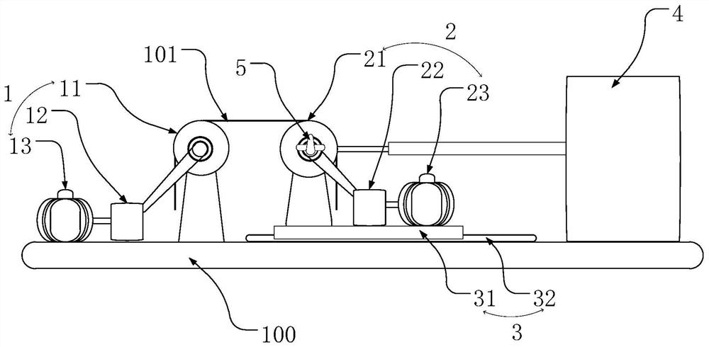
[0088] figure 1 It is a schematic diagram of the composition of the fiber rope pre-drawing device disclosed in Example 1.

[0089] In Embodiment 1, the device platform 100 is arranged horizontally, including a horizontally arranged plane for setting other components, wherein the first drafting assembly 1 is arranged on the left plane of the device platform 100, and on the right side of the first drafting assembly 1 The second drafting assembly 2 is provided, and the second drafting assembly 2 is set and installed on the movable assembly 3, and the movable assembly 3 is arranged on the device platform 100, and can move freely on the device platform 100; On the right side of the component 2, a drive component 4 is provided, and the tension detection component 5 is a torque sensor, which is adapted to be arranged on the rotating shaft of the second rotating component to detect the tension on the fiber rope;

[0090] Wherein, the first drafting assembly 1 includes a first rotatin...

Embodiment 2

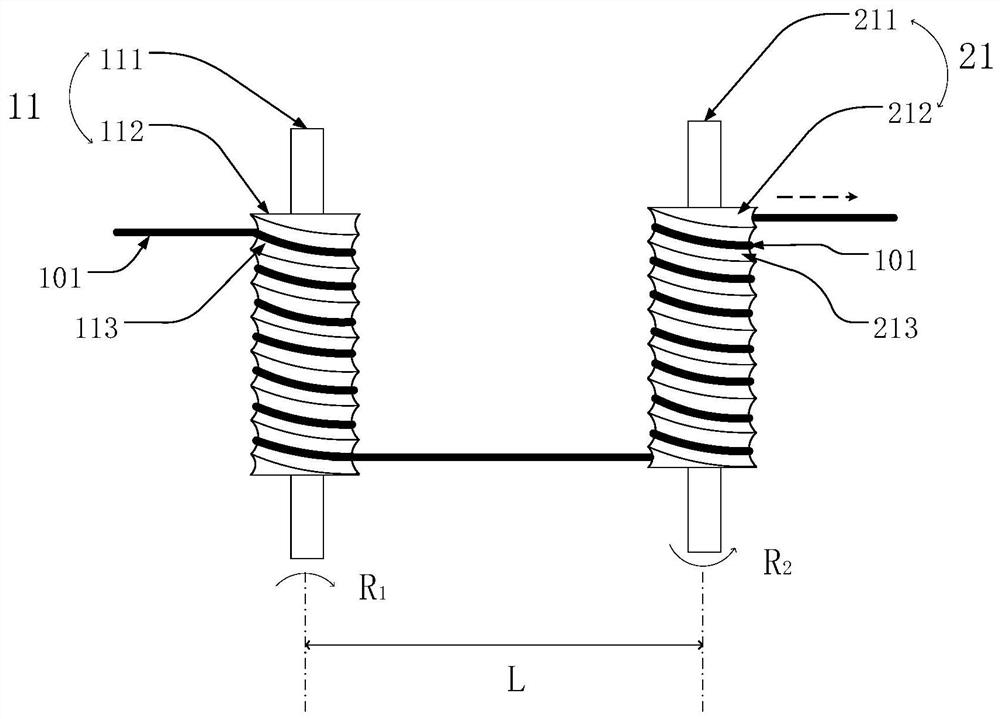
[0095] figure 2 It is a schematic diagram of the arrangement of the first rotating part and the second rotating part disclosed in the second embodiment.

[0096] In Embodiment 2, the first rotating part 11 includes a first rotating shaft 111 and a cylindrical first guide roller 112 fixedly connected to it. The surface of the first guide roller 112 is provided with a first continuous groove 113. The first continuous groove 113 is distributed on the surface of the first guide roller 112 in a spiral shape; the first rotating part 11 is set to rotate clockwise, as shown in the figure R 1 the first direction of rotation shown;

[0097] The second rotating part 21 includes a second rotating shaft 211 and a cylindrical second guide roller 212 fixedly connected to it. The surface of the second guide roller 112 is provided with a second continuous groove 213, and the second continuous groove 213 is distributed in a spiral shape. On the surface of the second guide roller 212; the sec...

Embodiment 3

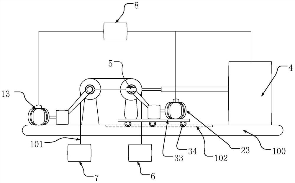
[0102] image 3 It is a schematic diagram of the composition of the fiber rope pre-drawing device disclosed in Example 3.

[0103] In Embodiment 3, the device platform 100 is arranged horizontally, including a horizontally arranged plane so as to arrange other components, wherein the first drafting assembly is arranged on the left plane of the device platform 100, and the right side of the first drafting assembly is provided with The second drafting assembly, the second drafting assembly is installed on the movable assembly, the movable assembly is arranged on the device platform 100, and can move freely on the device platform 100; on the right side of the second drafting assembly, A drive assembly 4 is provided, and the tension detection assembly 5 is a tension sensor, adapted to be arranged on the rotation shaft of the first rotating part and the rotating shaft of the second rotating part, so as to detect the tension on the fiber rope;

[0104] Wherein, the first drafting a...


PUM


Abstract

The fiber rope pre-drafting device includes: a device platform; a first drafting assembly, which is installed on the device platform, and the first drafting assembly includes at least one first rotating part for drafting the fiber rope; a movable assembly, which is set On the device platform, it is arranged to be movable on the device platform; the second drafting assembly is arranged and installed on the movable assembly, and the second drafting assembly includes at least one second rotating part for drafting the fiber rope, the second The rotating part is arranged in parallel with the first rotating part, and the distance between them is set to be adjustable; the driving assembly is arranged to be connected with the second rotating part, and is used to drive the movement of the second rotating part, and adjust the distance between the first rotating part and the first rotating part. The distance; the tension detection assembly is configured to detect the tension applied to the fiber rope; wherein the fiber rope is arranged on the first rotating part and the second rotating part, by adjusting the distance between the first rotating part and the second rotating part To adjust the tension of the fiber rope.

Description

technical field [0001] The application belongs to the technical field of fiber ropes, and in particular relates to a fiber rope pre-drawing device and a pre-drawing method. Background technique [0002] The rope will elongate after being loaded, and the elongation at break is another most important performance index of the rope after the breaking strength and linear density. Newly made braided or twisted fiber ropes, due to their dense structure, tend to have a large elongation when a load is applied, and part of the elongation is irrecoverable, and this irrecoverable elongation is actually the length of the rope. Structural elongation. For rope products that require high dimensional stability, such as hoisting ropes, electric traction ropes, sailing ropes, deep-sea buoy mooring cables, single-point and multi-point mooring cables for floating production, storage and offloading (FPSO), etc., There is a need to eliminate structural elongation of the rope during production. ...

Claims


Application Information

Patent Timeline
Patent Type & Authority Patents(China)
IPC IPC(8): D07B7/02
Inventor 朱林宁春林宋炳涛沈明陈兆华苏清磊李超
Owner SHANDONG ROPE TECH CO LTD
Why Eureka
Try Eureka