
Double-layer buoyant raft vibration reduction device and method

The technology of a vibration damping device and a floating raft is applied in the field of vibration damping equipment and vibration isolation. The effect of suppressing low frequency vibration

Pending Publication Date: 2021-04-16
SHANDONG UNIV
View PDF9 Cites 0 Cited by
  • Summary
  • Abstract
  • Description
  • Claims
  • Application Information

AI Technical Summary

Problems solved by technology

[0004] The inventors have learned that the existing floating raft vibration damping devices can consume the vibration energy on the transmission path and improve the vibration damping performance, but there are still some deficiencies, for example, most vibration damping devices can only Vibration reduction cannot effectively absorb and offset vibrations in different directions. The device occupies a large space, has a complex structure, is inconvenient to install and use, has poor corrosion resistance, and cannot be used in some complex environments. The effect is poor, and it cannot effectively isolate random vibrations of different frequencies

Method used


Image

  • Double-layer buoyant raft vibration reduction device and method
  • Double-layer buoyant raft vibration reduction device and method
  • Double-layer buoyant raft vibration reduction device and method

Examples


Embodiment 1

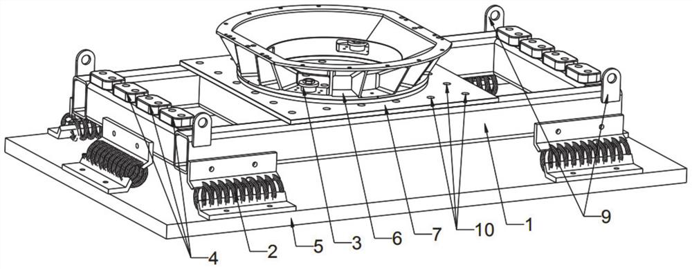
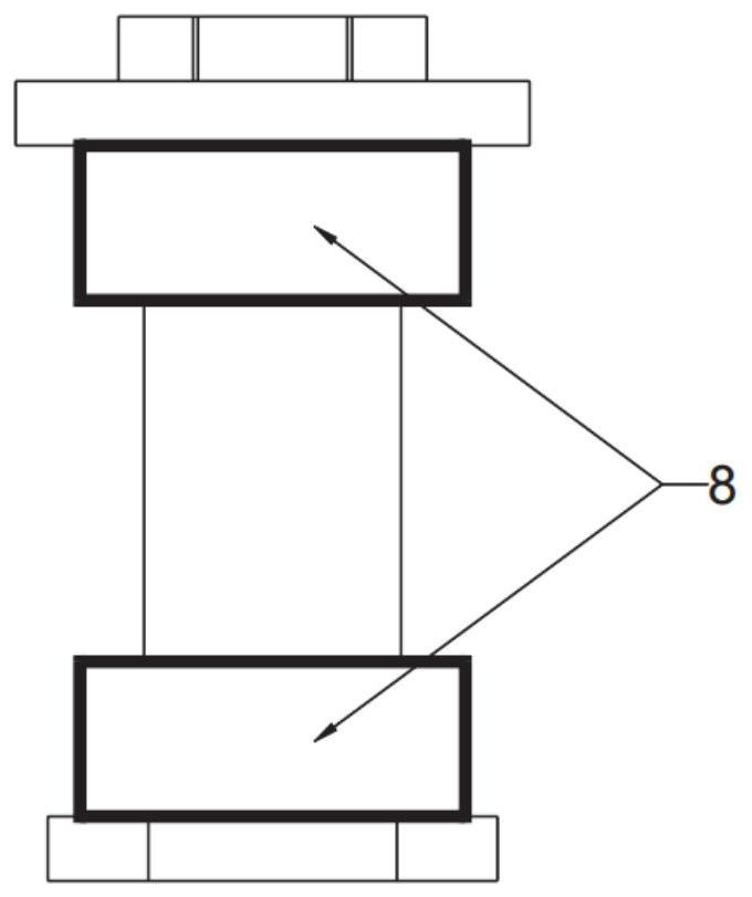
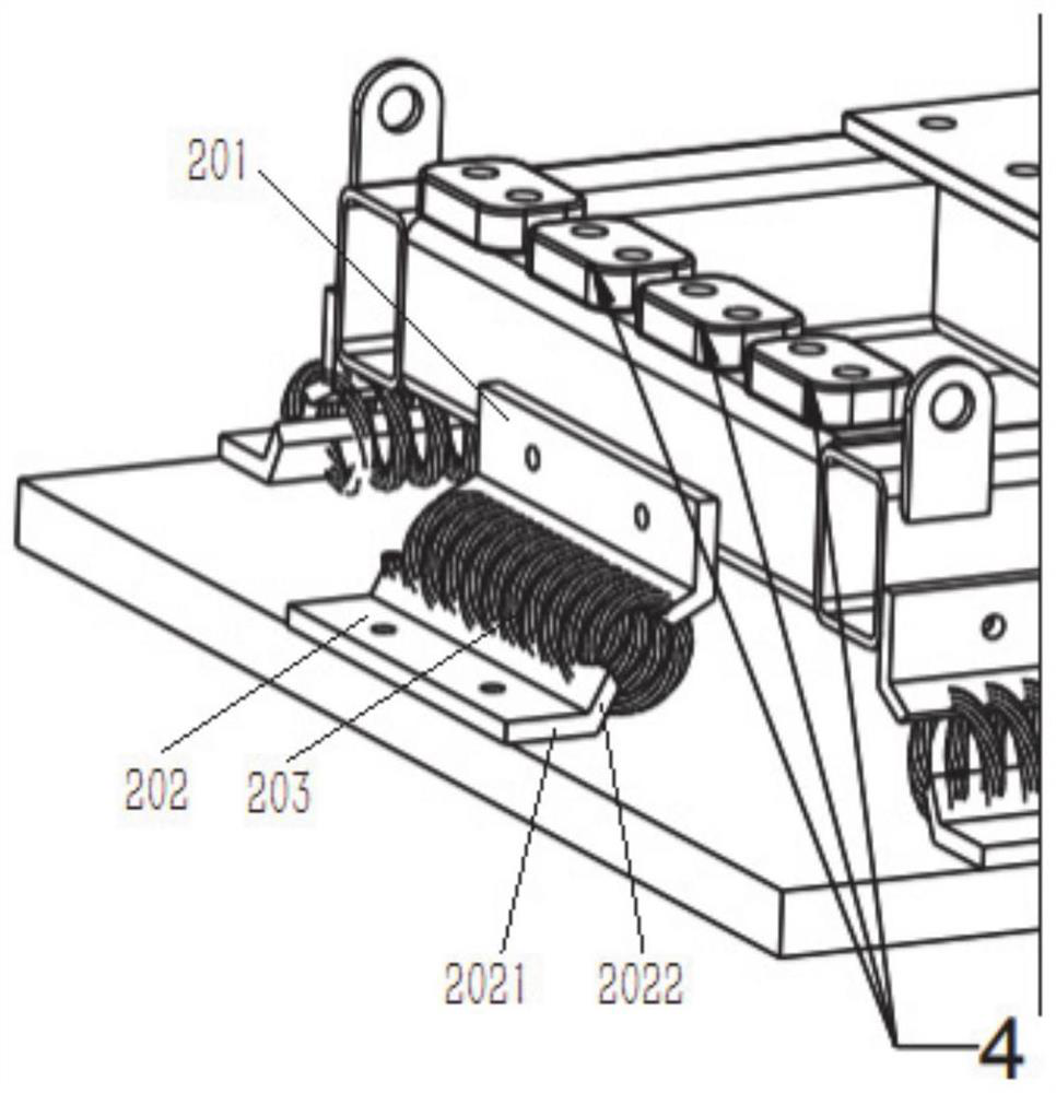
[0028] Such as Figure 1-Figure 3 As shown, this embodiment provides a double-layer floating raft vibration damping device, which includes a base 5, a raft frame 1 and a transfer tool 6 arranged sequentially from bottom to top, and the base 5 and raft frame 1 are damped by two sets of steel wire ropes. 2, the helical centerlines of the steel wire ropes 203 in the two groups of steel wire rope dampers 2 are arranged vertically and horizontally to each other, and the steel wire rope dampers 2 are installed obliquely to absorb vibration in any direction between the base 5 and the raft frame 1; The raft frame 1 and the transfer tooling 6 are connected by a vibration-absorbing connector 3 with a vertical axis. The two ends of the vibration-damping connector 3 are provided with metal rubber gaskets 8, which can absorb the raft frame 1 and the transfer tooling. 6 between vertical vibrations.

[0029] It can be understood that the wire rope damper here forms a first-stage shock absor...

Embodiment 2

[0048] This embodiment provides a double-layer floating raft vibration reduction method, which utilizes the double-layer floating raft vibration reduction device described in Embodiment 1, including the following steps:

[0049] The base 5 is arranged at the bottom surface of the support, and the base 5 receives the vibration from the bottom surface of the support;

[0050] When the vibration of the base 5 is transmitted to the raft 1, the vibration in any direction can be decomposed into component forces along the horizontal and vertical directions in the space, and weakened by the wire rope shock absorber 2;

[0051] The vibration weakened by the wire rope damper 2 is transmitted to the raft frame 1, and the vibration of the raft frame 1 is vertically attenuated by the vibration-damping connector 3 and then transmitted to the transfer tool 6, which is used to install the equipment to be damped .


PUM


Abstract

The invention relates to a double-layer buoyant raft vibration reduction device and method. The double-layer buoyant raft vibration reduction device comprises a base, a raft frame and a transfer tool which are sequentially arranged from bottom to top. The base and the raft frame are connected through two sets of steel wire rope vibration reducers. The spiral center lines of steel wire ropes in the two sets of steel wire rope vibration reducers are perpendicular to each other and are both horizontally arranged. The steel wire rope vibration reducers are used for absorbing vibration between the base and the raft frame in any direction. The raft frame and the transfer tool are connected through a vibration reduction connecting piece with the vertical axis. Metal rubber gaskets are arranged at the two ends of the vibration reduction connecting piece and can absorb vibration between the raft frame and the transfer tool in the vertical direction.

Description

technical field [0001] The disclosure belongs to the technical field of vibration isolation and damping equipment, and in particular relates to a double-layer floating raft vibration damping device and method. Background technique [0002] The statements herein merely provide background information related to the present disclosure and do not necessarily constitute prior art. [0003] Modern precision equipment is very sensitive to the working environment, especially the vibration environment. The harsh vibration environment will not only threaten the long-term reliable operation of the equipment, but also affect its normal work. In engineering practice, precision equipment is usually installed on a vibration-damping platform, and the vibration environment in which it is located is improved through the vibration-damping platform. The vibration-damping floating raft is a typical vibration-damping platform, which is very suitable for vibration-damping large-scale equipment d...

Claims


Application Information

Patent Timeline
Patent Type & Authority Applications(China)
IPC IPC(8): F16F15/08F16F15/28
Inventor 孙述鹏王锋会冯维明冯玥鹏
Owner SHANDONG UNIV
Learn More