
Flow computer capable of automatically correcting time and automatically diagnosing flowmeter

A technology of flow computer and automatic diagnosis, which is applied in the direction of liquid/fluid solid measurement, measuring device, test/calibration device, etc. It can solve the problems of high resource occupation of flow computer on site, inaccurate writing time, and time delay, etc. Achieve the effects of reducing on-site resource occupancy, accurate and reliable time, and eliminating poor compatibility

Pending Publication Date: 2021-04-16
南京深度系统工程有限公司
View PDF0 Cites 0 Cited by
  • Summary
  • Abstract
  • Description
  • Claims
  • Application Information

AI Technical Summary

Problems solved by technology

[0003] At present, in order to realize the online diagnosis function of some flowmeters, an additional local or remote diagnosis system is added to the metering system, including a data acquisition server and a data processing server. The parameters are sent to the data processing server, and the data processing server displays the diagnosis results after calculation and stores the diagnosis report in the local server. This method has the disadvantages of poor compatibility, poor real-time performance, high occupation of on-site traffic computer resources, and high cost.
[0004] In addition, under normal circumstances, the time of the flow computer will drift after a period of use, so it is necessary to periodically correct the time. The traditional time correction method is to send the flow computer to the flow computer through the upper device (computer or PLC) of the local or control center. Write time, but this method requires the clock of the host device to be very accurate, and there is a time delay. In the case of writing time to multiple flow computers, the delay will be accumulated and the written time will be inaccurate

Method used


Image

  • Flow computer capable of automatically correcting time and automatically diagnosing flowmeter
  • Flow computer capable of automatically correcting time and automatically diagnosing flowmeter

Examples


Embodiment Construction

[0020] In order to have a further understanding of the purpose, structure, features, and functions of the present invention, the following detailed descriptions are provided in conjunction with the embodiments.

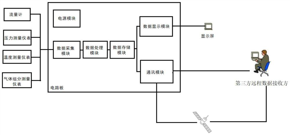
[0021] like Figure 1-Figure 2 As shown, a flow computer for automatic timing and automatic diagnosis flowmeter includes a data processing module and a power supply module. The data processing module includes an instantaneous flow calculation program module, an accumulated flow calculation program module, and a data acquisition module. storage module, data display module, and communication module; the data acquisition module is electrically connected to the data processing module and the data storage module through the circuit board in turn, and the data storage module is electrically connected to the data display module and the communication module through the circuit board respectively. The power supply module is connected with the circuit board to provide power for...


PUM


Abstract

The invention provides a flow computer capable of automatically correcting time and automatically diagnosing a flowmeter. The flow computer comprises a data processing module, a power module, a data acquisition module, a data storage module, a data display module and a communication module. The data acquisition module is electrically connected with the data processing module and the data storage module in sequence through the circuit board, the data storage module is electrically connected with the data display module and the communication module through the circuit board, and the power supply module is connected with the circuit board to supply power to the data acquisition module, the data storage module, the data display module, the communication module and the data processing module; the data processing module further comprises a flowmeter automatic diagnosis module and a time calibration module. The flowmeter is diagnosed on line in real time through the diagnosis module function of the flow computer, flowmeters of various types are supported, the defect that the compatibility of multiple devices and multiple servers is poor is overcome, the field resource occupancy rate is reduced, and the cost is reduced.

Description

technical field [0001] The invention relates to the field of flow computers for trade transfer, in particular to a flow computer for automatic timing and automatic diagnosis of flowmeters. Background technique [0002] Flow calculators are mainly used in gas or liquid custody transfer fields, also known as flow totalizers, especially for natural gas / oil product trade measurement. [0003] At present, in order to realize the online diagnosis function of some flowmeters, an additional local or remote diagnosis system is added to the metering system, including a data acquisition server and a data processing server. The parameters are sent to the data processing server, and the data processing server displays the diagnosis results after calculation and stores the diagnosis report in the local server. This method has the disadvantages of poor compatibility, poor real-time performance, high occupation of on-site traffic computer resources, and high cost. [0004] In addition, und...

Claims


Application Information

Patent Timeline
Patent Type & Authority Applications(China)
IPC IPC(8): G01F25/00
Inventor 汪纯
Owner 南京深度系统工程有限公司
Learn More