Drawer type intelligent optical fiber distribution frame

A technology of intelligent optical fiber and distribution frame, applied in the direction of fiber mechanical structure, etc., can solve problems such as insufficient optical cable redundancy, optical fiber distribution box cannot be pulled out smoothly, affecting the operation accuracy of operation and maintenance personnel, etc., so as to reduce work pressure. , Improve the efficiency of operation and maintenance work

Pending Publication Date: 2021-04-16
安徽省富林电子科技有限公司
View PDF0 Cites 0 Cited by
  • Summary
  • Abstract
  • Description
  • Claims
  • Application Information

AI Technical Summary

Problems solved by technology

However, in actual work, the optical cable at the back of the optical fiber distribution box often does not have enough margin during installation, resulting in the failure of the optical fiber distribution box to be pulled out smoothly. If the optical fiber distribution box is forcibly pulled out, the entire optical cable may be completely interrupted. This also allows the operation and maintenance personnel to only operate the fiber optic distribution box in a narrow enclosure
Due to the narrow operating space, it will also affect the operation accuracy of the operation and maintenance personnel. There may be phenomena such as the gaps on the fiber jumper not being aligned, and the jumper fiber being inserted into the wrong port, etc., which also cause certain hidden dangers to the safe operation of the optical communication system.

Method used


Image

  • Drawer type intelligent optical fiber distribution frame
  • Drawer type intelligent optical fiber distribution frame
  • Drawer type intelligent optical fiber distribution frame

Examples


Embodiment Construction

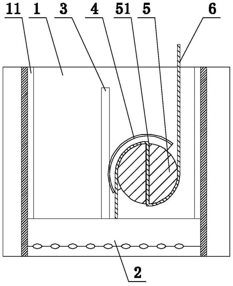
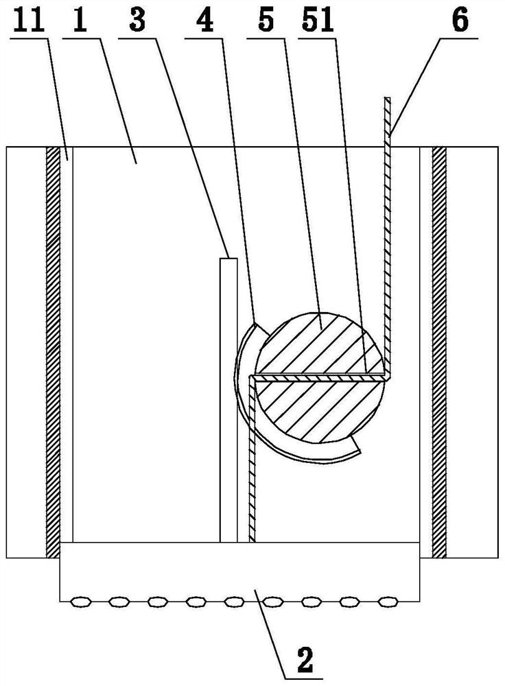
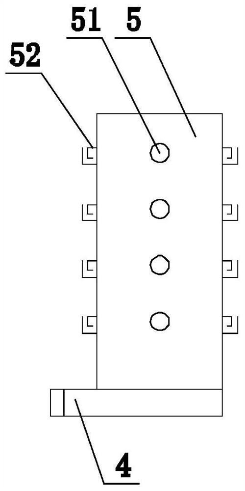
[0018] like Figure 1-3 shown, figure 1 It is a schematic structural diagram of a drawer-type intelligent optical fiber distribution frame where the distribution box is retracted into the casing. figure 2 It is a schematic structural diagram of a drawer-type intelligent optical fiber distribution frame drawn out of the casing of the distribution box proposed by the present invention. image 3 It is a structural schematic diagram of a winding column of a drawer-type intelligent optical fiber distribution frame proposed by the present invention.

[0019] refer to Figure 1-3 , a drawer type intelligent optical fiber distribution frame proposed by the present invention includes a housing 1, at least one wiring box 2 and a pay-off mechanism for adjusting the length of the optical fiber 6. The wiring box 2 can be horizontally slidably installed on the housing 1;

[0020] The pay-off mechanism includes a gear 4, a rack 3 and a winding column 5;

[0021] The rack 3 is horizonta...


PUM


Abstract

The invention discloses a drawer type intelligent optical fiber distribution frame which comprises a shell, at least one distribution box and a pay-off mechanism used for adjusting the use length of an optical fiber, and the distribution box can be horizontally installed in the shell in a sliding mode. The pay-off mechanism comprises a gear, a rack and a winding post; the rack is horizontally arranged in the shell, fixedly installed on the distribution box and located on the rear side of the distribution box, the gear is horizontally and rotationally installed in the shell and meshed with the rack, the winding column is coaxially and fixedly installed on the gear, and at least one through positioning hole is formed in the side wall of the winding column. According to the drawer type intelligent optical fiber distribution frame provided by the invention, the use length of the optical fiber can be automatically adjusted according to the position of the distribution box, so that the distribution box can be smoothly put into and pulled out of the shell. The distribution box can be plugged in and pulled out in a time-saving and labor-saving manner, the phenomenon that optical fibers are broken due to the fact that a traditional distribution frame forcibly pulls out the distribution box is avoided, and the phenomena that due to the narrow operation space, notches in jumper fibers cannot be aligned, and the jumper fibers are wrongly plugged into ports are avoided. The operation and maintenance work efficiency is improved.

Description

technical field [0001] The invention relates to the technical field of distribution frame design, in particular to a drawer type intelligent optical fiber distribution frame. Background technique [0002] With the rapid development of the smart grid, the dependence on the optical communication network is also increasing. In the daily operation and maintenance of the optical communication network, a large number of fiber jumper operations need to be performed on the optical fiber distribution frame. The optical fiber distribution box of the traditional distribution frame is usually installed in the casing in a drawer-like manner. When the optical fiber distribution box needs to be operated, the optical fiber distribution box can be operated by pulling it out of the casing. However, in actual work, the optical cable behind the optical fiber distribution box is often not left enough when it is installed, so that the optical fiber distribution box cannot be pulled out smoothly. ...

Claims


Application Information

Patent Timeline
Patent Type & Authority Applications(China)
IPC IPC(8): G02B6/44
Inventor 韦玉林
Owner 安徽省富林电子科技有限公司
Why Eureka
Try Eureka