Electronic equipment

A technology for electronic equipment and equipment, applied in the direction of instruments, chassis/cabinet/drawer parts, installation, etc., can solve the problems of the overall height of the optical module and the inability to meet the requirements of light and thin electronic equipment, and achieve the goal of meeting the requirements of light and thin reduce the overall height and ensure the effect of image quality

Active Publication Date: 2022-07-08
VIVO MOBILE COMM CO LTD
View PDF10 Cites 0 Cited by
  • Summary
  • Abstract
  • Description
  • Claims
  • Application Information

AI Technical Summary

Problems solved by technology

[0003] This application discloses an electronic device to solve the problem that the optical module cannot meet the demand for light and thin electronic devices due to the high overall height

Method used


Image

  • Electronic equipment
  • Electronic equipment
  • Electronic equipment

Examples


Embodiment Construction

[0032] In order to make the objectives, technical solutions and advantages of the present application clearer, the technical solutions of the present application will be clearly and completely described below with reference to the specific embodiments of the present application and the corresponding drawings. Obviously, the described embodiments are only a part of the embodiments of the present application, but not all of the embodiments. Based on the embodiments in the present application, all other embodiments obtained by those of ordinary skill in the art without creative efforts shall fall within the protection scope of the present application.

[0033] The technical solutions disclosed in the various embodiments of the present application will be described in detail below with reference to the accompanying drawings.

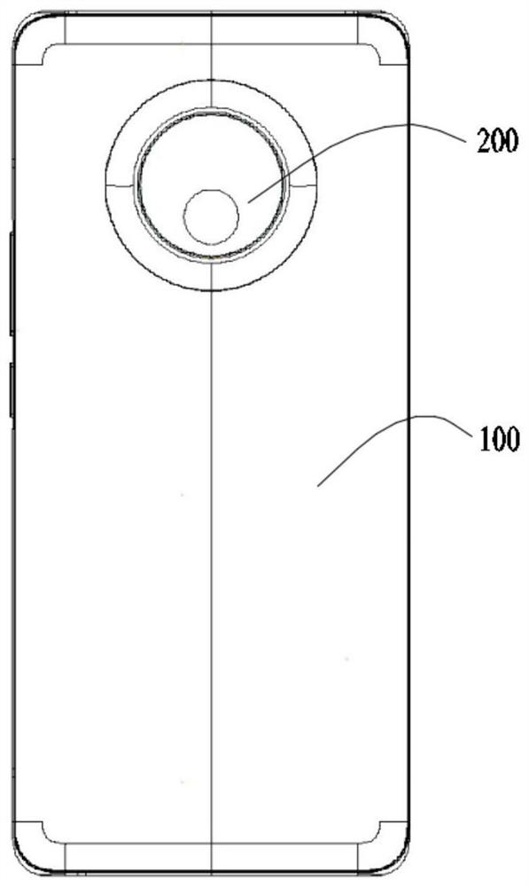
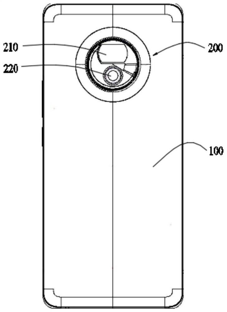
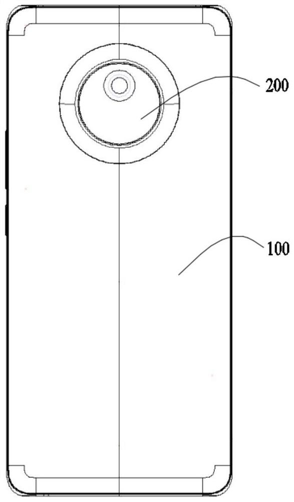
[0034] Please refer to figure 1 and Figure 7 , the embodiment of the present invention discloses an electronic device, including a device casing 100 and ...


PUM


Abstract

The electronic device disclosed in the present application includes a device housing and an optical module. The device housing is provided with a first through hole, and the optical module includes a module body fixed in the device housing and a first through hole rotatably arranged in the first through hole. The lens assembly, by rotating and extending the first lens assembly relative to the device housing, causes the first lens assembly to form a dislocation with the main body of the module when retracting, thereby reducing the height of the optical module in a non-shooting state, and making the first lens When the assembly is extended, it is opposite to the main body of the module, so as to raise the height of the optical module in the shooting state to ensure the shooting quality. To sum up, the optical module can reduce the overall height of itself while ensuring the imaging quality, thereby meeting the needs of light and thin electronic devices.

Description

technical field [0001] The present application relates to the technical field of communication devices, and in particular, to an electronic device. Background technique [0002] With the improvement of user demands, the performance of electronic devices continues to be optimized. More and more electronic devices are equipped with optical modules with more powerful shooting functions. In order to improve the shooting effect, the area of ​​the photosensitive chip of the current optical module is getting larger and larger, and the lens of the optical module is getting longer and longer. This results in an increasing height of the optical module. We know that the current electronic devices are developing in a thinner and thinner direction. Obviously, the higher height of the optical module will conflict with the development trend of thin and light electronic devices. SUMMARY OF THE INVENTION [0003] The present application discloses an electronic device to solve the proble...

Claims


Application Information

Patent Timeline
Patent Type & Authority Patents(China)
IPC IPC(8): H05K5/02G02B7/02G03B30/00
CPCG03B30/00G02B7/02
Inventor 冯志新于阳
Owner VIVO MOBILE COMM CO LTD
Why Eureka
Try Eureka