Cooling module

A heat dissipation module and vibrating element technology, which is applied in the direction of cooling/ventilation/heating transformation, etc., can solve problems such as high noise, short service life, and material restrictions, and achieve the effect of reducing volume and thickness and improving space utilization

Active Publication Date: 2016-05-18
DELTA ELECTRONICS INC
View PDF12 Cites 0 Cited by
  • Summary
  • Abstract
  • Description
  • Claims
  • Application Information

AI Technical Summary

Problems solved by technology

[0012] The purpose of the present invention is to provide a heat dissipation module to solve the defects of the existing heat dissipation modules such as inability to reduce volume and thinness, excessive noise, short service life and easy limitation of materials used.

Method used


Image

  • Cooling module
  • Cooling module
  • Cooling module

Examples


Embodiment Construction

[0055] Some typical embodiments embodying the features and advantages of the present invention will be described in detail in the description in the following paragraphs. It should be understood that the present invention is capable of various changes in different forms without departing from the scope of the present invention, and that the description and drawings are illustrative in nature and are not intended to limit the present invention.

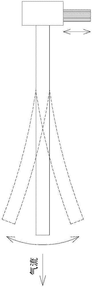
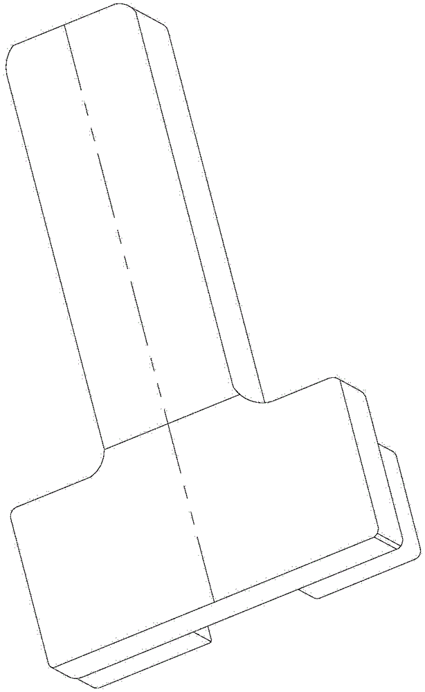
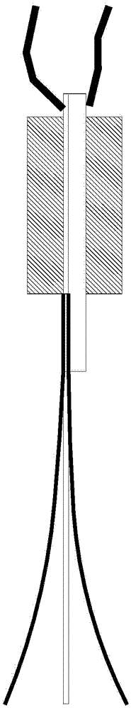
[0056] see Figure 7 and Figure 8 ,in Figure 7 It is a structural schematic diagram of the heat dissipation module of the first preferred embodiment of the present invention; and Figure 8 for Figure 7 The diagram of the connection relationship between the vibrating element, bracket and drive unit of the heat dissipation module shown. The cooling module 1 of the present invention can be set in thin and portable electronic devices (not shown), such as but not limited to tablet computers, e-books, and can be used as an airflow gen...


PUM


Abstract

The invention discloses a heat-dissipating module disposed in an electronic device. The heat-dissipating module comprises at least one vibrating element, a support, and a driving unit. The vibrating element comprises an actuation portion and a free end portion. The support is connected with the actuation portion of the at least one vibrating element. The driving unit is connected with the support and drives the support to move. The driving unit drives the support to move and enables the support to drive the actuation portion of the vibrating element to move. Therefore, displacement is generated on the free end portion of the vibrating element because of resonance. And thus, airflow is generated at the free end portion of the vibrating element in order to dissipate heat in the electronic device.

Description

technical field [0001] The invention relates to a heat dissipation module, in particular to a heat dissipation module which utilizes resonance effect to generate air flow. Background technique [0002] Since many electronic devices are becoming thinner, portable and more efficient, electronic devices must be equipped with various high-power or high-density electronic components in their limited internal space. Therefore, when the electronic device is running If the heat generated by the electronic components cannot be effectively removed, the electronic device will be prone to instability and affect the reliability of the product. Therefore, heat dissipation and temperature control have become one of the important issues of the current electronic device. [0003] Generally, heat dissipation methods used in electronic devices can be divided into active heat dissipation and passive heat dissipation. Active heat dissipation usually installs an axial flow fan or a blower fan in...

Claims


Application Information

Patent Timeline
Patent Type & Authority Patents(China)
IPC IPC(8): H05K7/20
Inventor 游锦祥徐富美
Owner DELTA ELECTRONICS INC
Why Eureka
Try Eureka