Paralimbal laser probe

A technology of probe and edge, applied in the field of laser probe in trabeculoplasty, which can solve problems such as cell death

Pending Publication Date: 2021-04-16
欧科维斯私人有限公司
View PDF9 Cites 0 Cited by
  • Summary
  • Abstract
  • Description
  • Claims
  • Application Information

AI Technical Summary

Problems solved by technology

However, firing a laser at each of these points along the TM causes the death of many

Method used


Image

  • Paralimbal laser probe
  • Paralimbal laser probe
  • Paralimbal laser probe

Examples


example 1

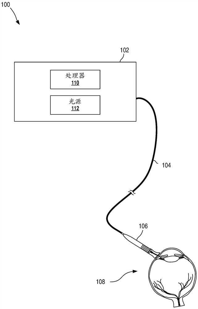
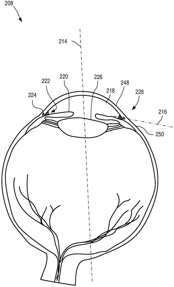
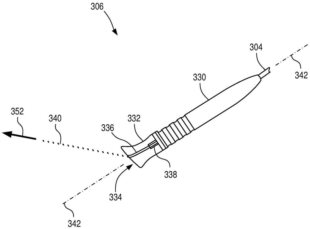
[0087] Example 1 is a limbal probe comprising: a probe tip shaped to match the surface of the eye at or near the limbus of an eye having an applicator Lyme's canal and trabecular meshwork; and a waveguide positioned within the probe tip to convey electromagnetic radiation from a source of electromagnetic radiation to the eye, wherein the waveguide is oriented to align with the Schlemm's canal and trabecular meshwork The mesh intersects the treatment paths to guide the electromagnetic radiation.

example 2

[0088] Example 2 is the probe of example 1, wherein the waveguide is positioned further within the probe tip such that the treatment path further intersects peripheral tissue of the eye.

example 3

[0089] Example 3 is the probe of example 1 or example 2, wherein the waveguide is positioned further within the probe tip such that the treatment path further intersects corneal tissue of the eye.


PUM


Abstract

A probe as disclosed herein is capable of treating both the Schlemm's canal (SC) and the trabecular meshwork (TM), or both the pars plicata and the iris root site of the eye, with electromagnetic radiation (e.g., laser light) to improve aqueous humor outflow and thus decrease intraocular pressure (IOP). The laser probe can include a tip capable of being placed on an eye, such as on a corneal limbus or a scleral limbal area of the eye. The tip can include an optical waveguide angled to direct laser light through both the SC and TM, or both the pars plicata and the iris root site of the eye. The laser light can be continuous or pulsed, and can be configured to provide appropriate therapy to both the SC and TM, or to both the pars plicata and the iris root site. The laser probe can facilitate performing trans-scleral trabeculoplasty treatment, especially trans-scleral Schlemm trabeculoplasty, and performing iridoplasty treatment.

Description

technical field [0001] The present disclosure relates generally to ophthalmic treatments, and more particularly to laser probes for trabeculoplasty. Background technique [0002] Higher than normal intraocular pressure (IOP) is considered to be an important factor in the development or exacerbation of various eye diseases such as glaucoma. Higher-than-normal intraocular pressure can be reduced or avoided by increasing the outflow of aqueous humor from the eye. The aqueous humor carried by the aqueous humor outflow path passes through the trabecular meshwork (TM) from the anterior chamber, enters the Schlemm's canal (SC), and then flows into the blood system. [0003] Argon laser trabeculoplasty (ALT) and selective laser trabeculoplasty (SLT) are two procedures used to treat various eye conditions by increasing the outflow of aqueous humor from the eye. technology. Typically, ALT and SLT operate by focusing electromagnetic energy (e.g., laser light) onto the TM, which caus...

Claims


Application Information

Patent Timeline
IPC IPC(8): A61F9/008
CPCA61F9/00821A61F2009/00868A61F2009/00891A61F9/0079A61F9/008A61F9/009A61F2009/00865A61F2009/00872A61F2009/00874A61F2009/00876
Inventor 切力·翠·玲·邱乔尔·M·阿杜安
Owner 欧科维斯私人有限公司
Why Eureka
Try Eureka