

Pesticide spraying equipment with anti-freezing function for garden gardening
A technology for pesticide spraying and gardening, applied in the field of pesticide spraying equipment with antifreeze function, can solve the problems of waste of resources, inability to spray, waste of manpower, etc., and achieve the effects of improving uniform mixing, preventing uneven mixing, and adjusting the spraying range
- Summary
- Abstract
- Description
- Claims
- Application Information
AI Technical Summary
Problems solved by technology
Method used
Image

Examples
Embodiment Construction
[0025] The following will clearly and completely describe the technical solutions in the embodiments of the present invention with reference to the accompanying drawings in the embodiments of the present invention. Obviously, the described embodiments are only some, not all, embodiments of the present invention. Based on the embodiments of the present invention, all other embodiments obtained by persons of ordinary skill in the art without making creative efforts belong to the protection scope of the present invention.
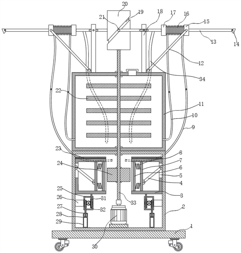
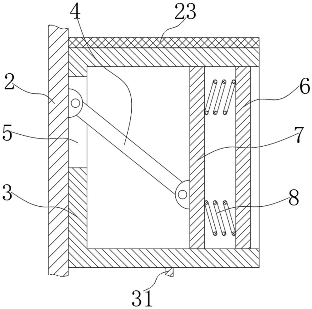
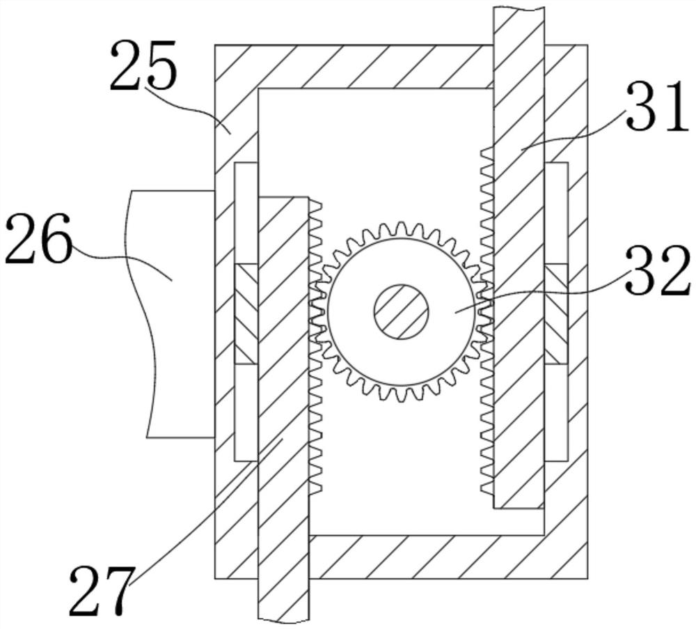
[0026] see Figure 1 to Figure 5 , the present invention provides a technical solution: a pesticide spraying equipment with antifreeze function for gardening, including a base 1, a support shell 2 is fixed on the top of the base 1, and a liquid medicine tank 11 is fixed on the top of the support shell 2, The top of the liquid medicine tank 11 is provided with a spraying mechanism that can adjust the spraying range, and the inside of the supporting shell 2 is p...
PUM
 Abstract
Description
Claims
Application Information