Clip bin as well as clip push plate and clip applier used in matched way

A technique for applying clamps and pushing plates, which is applied in the field of medical devices and can solve problems such as inconvenience in use

Pending Publication Date: 2021-04-20
JIANGSU NRS MEDICAL INSTR CO LTD
View PDF0 Cites 4 Cited by
  • Summary
  • Abstract
  • Description
  • Claims
  • Application Information

AI Technical Summary

Problems solved by technology

[0003] In the prior art, most of the clip appliers are single-shot clip appliers. Although this kind of clip applier has a simple structure, it is very inconvenient to use the clip applier because it needs to be filled multiple times in the operation where the clip applier needs to be used multiple times.

Method used


Image

  • Clip bin as well as clip push plate and clip applier used in matched way
  • Clip bin as well as clip push plate and clip applier used in matched way
  • Clip bin as well as clip push plate and clip applier used in matched way

Examples


Embodiment 1

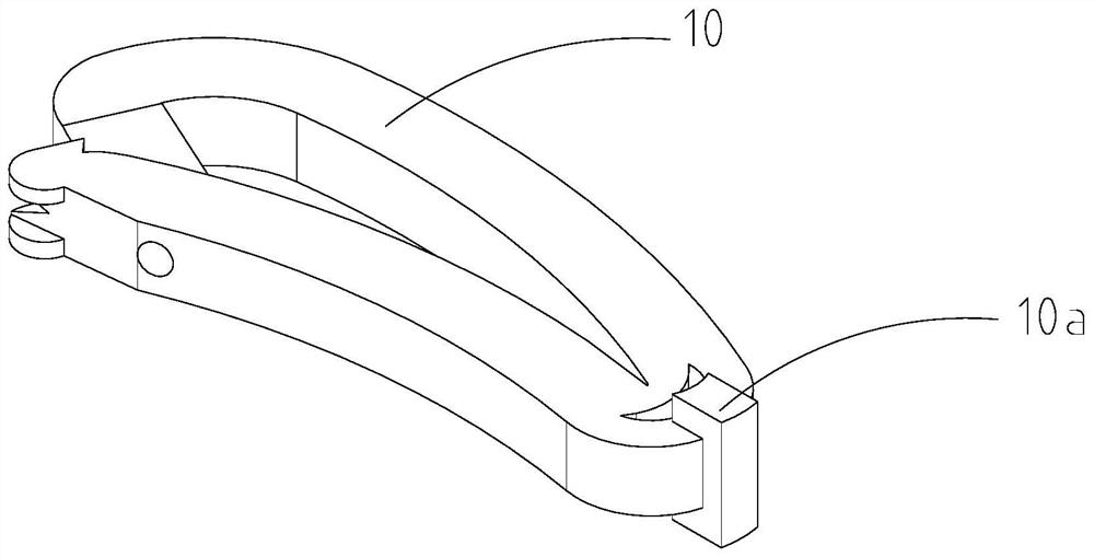
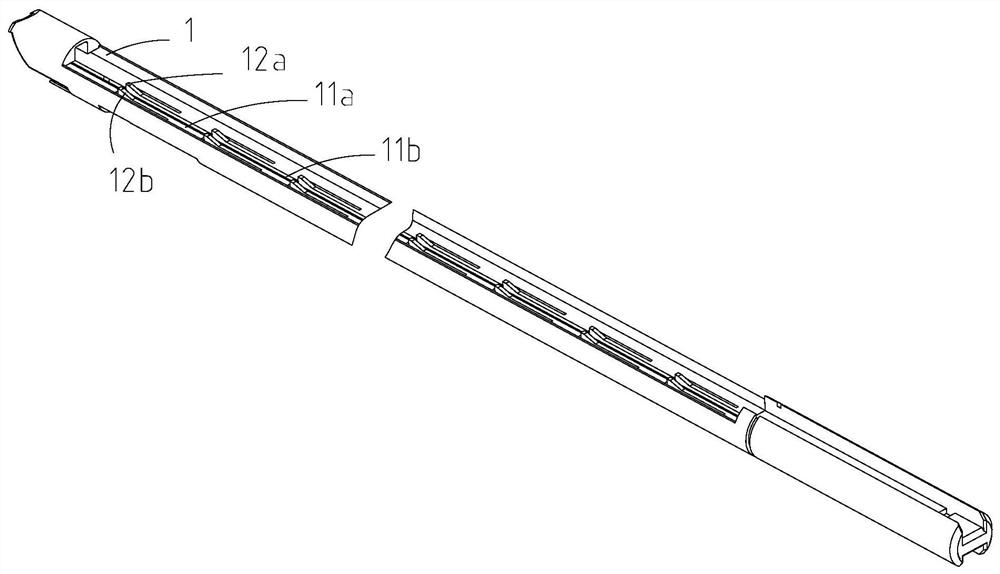
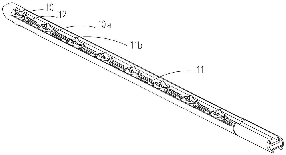
[0027] Such as Figure 1~3 Shown, a kind of clip bin, is used for placing ligation clip 10, and it comprises bin body 1, and bin body 1 has the bin chamber 11 that places ligation clip 10, and bin body 1 forms the bottom wall 11a of bin chamber 11 to be provided with protruding Bottom wall 11a, at least two stoppers 12 that are elastic and arranged along the length direction of the chamber; wherein,

[0028] The blocking portion 12 is adapted to bear against the rear portion of the corresponding ligation clip 10 placed in the chamber 11 to prevent the ligation clip 10 from moving backward along the length direction of the chamber cavity and to contact the blocking portion when the ligation clip 10 moves forward along the length direction of the chamber chamber At 12 o'clock, it deforms toward the bottom wall so that the ligation clip 10 passes through the stopper 12 .

[0029] In this embodiment, there may be multiple blocking parts 12 .

[0030] Specifically, such as figur...

Embodiment 2

[0036] Such as Figure 4 As shown, a clip push plate is used in conjunction with the clip bin in the first embodiment. It includes a plate body 2, which is provided with a protruding plate body 2, has elasticity and is arranged along the length direction of the plate body. At least two pushing parts 21; wherein,

[0037] The push part 21 is adapted to deform toward the plate body when the plate body 2 moves backward along the length direction and contacts the corresponding ligation clip 10 placed in the chamber 11 so that the push part 21 passes through the ligation clip 10 and is suitable for moving the plate body 2 along the When the length direction moves forward and touches the rear portion of the ligation clip 10, the ligation clip 10 is pushed to move forward together.

[0038] In this embodiment, the number of pushing parts 21 can be set in multiples.

[0039] Such as figure 1 , 4 As shown, the ligation clip 10 is provided with a limit block 10a;

[0040] The plate...

Embodiment 3

[0047] A clamp applier comprising:

[0048] The clip bin in embodiment one;

[0049] And clamp push plate among the embodiment two.


PUM


Abstract

The invention discloses a clip bin as well as a clip push plate and a clip applier used in a matched way. The clip bin is used for containing a ligature clip and comprises a bin body; the bin body is provided with a bin cavity for containing the ligature clip; the bottom wall, forming the bin cavity, of the bin body is provided with at least two blocking parts which protrude out of the bottom wall, have elasticity and are arranged in the length direction of the bin cavity; and the blocking parts are suitable for abutting against the rear portion of the corresponding ligature clamp arranged in the bin cavity so as to prevent the ligature clamp from moving backwards in the length direction of the bin cavity and deforming in the direction of the bottom wall when the ligature clamp moves forwards in the length direction of the bin cavity to make contact with the blocking parts so as to enable the ligature clamp to pass through the blocking parts. The convenience is provided for the clip applier to realize continuous application of the ligature clip, and the phenomenon that the ligature clip retracts is avoided.

Description

technical field [0001] The invention relates to a clip bin, a clip push plate and a clip applicator used in conjunction with it, and belongs to the technical field of medical instruments. Background technique [0002] At present, in human abdominal surgery, preventing bleeding as much as possible is a major factor for the ultimate success of the operation. At present, clip appliers are mainly used for ligation of blood vessels or tissues in minimally invasive surgical operations. [0003] In the prior art, most of the clip appliers are single-shot clip appliers. Although this clip applier has a simple structure, it is very inconvenient to use the clip applicators many times in operations requiring multiple use of the clip applicators. Contents of the invention [0004] The technical problem to be solved by the present invention is to overcome the defects of the prior art, and provide a clip magazine, which provides convenience for the clip applier to realize successive lig...

Claims


Application Information

Patent Timeline
Patent Type & Authority Applications(China)
IPC IPC(8): A61B17/128
Inventor 王思清魏家富程先本李伟李钧朱嘉伟
Owner JIANGSU NRS MEDICAL INSTR CO LTD
Why Eureka
Try Eureka