A component cleaning device and method
A technology for cleaning devices and components, applied in cleaning methods and utensils, cleaning methods using gas flow, chemical instruments and methods, etc., can solve the problem that the cleaning station is far away from the final assembly area, the process of cleaning-transfer-assembly is cumbersome, Not suitable for large-scale production and other problems, to avoid large-scale turbulence, facilitate assembly, and reduce the spread of dust
- Summary
- Abstract
- Description
- Claims
- Application Information
AI Technical Summary
Problems solved by technology
Method used
Image

Examples
Embodiment 1
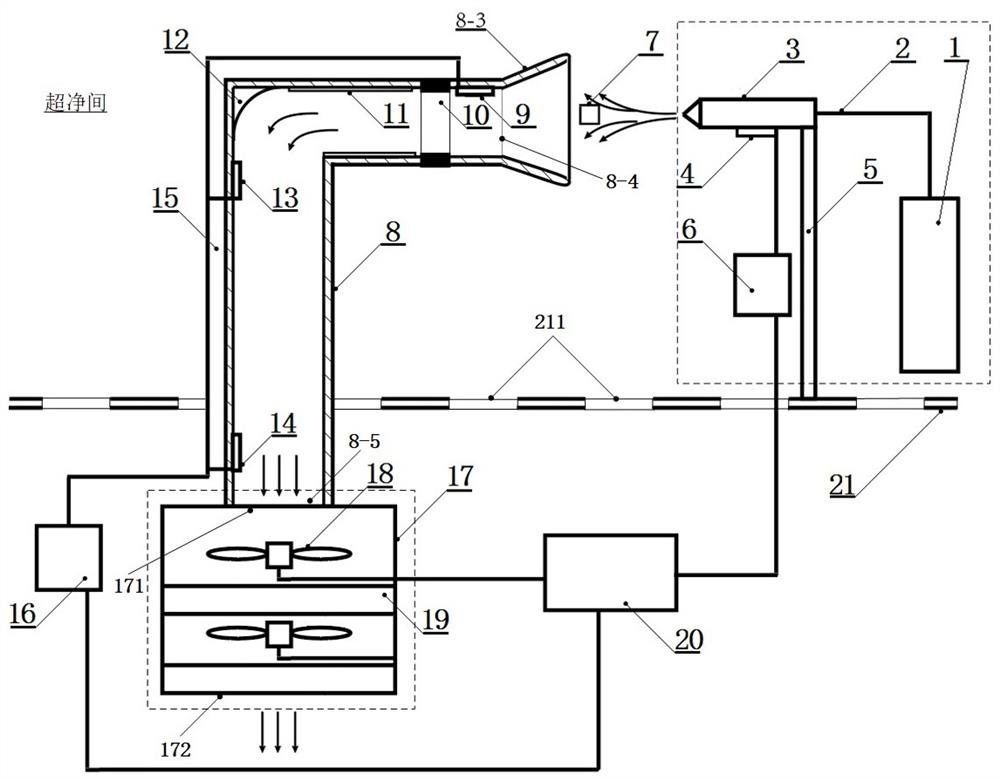
[0032] like figure 1 As shown, the embodiment of the present invention provides a component cleaning device, which is used in an ultra-clean room with a cleanliness level above IOS4 to clean a component to be cleaned. There is a clean air flow blown from top to bottom in the ultra-clean room. It also has a return air floor 21 including ventilation holes 211. Below the return air floor 21 is a return air layer. Under the action of the ventilation system in the ultra-clean room, the air entering the return air layer is filtered by the fan on the top of the ultra-clean room again. unit, thereby generating a downward direction of clean air flow, the process can be found in "A review of cleanroom microflora: types, trends, and patterns". PDA J Pharm Sci Technol . 65(4): 392–403. The component cleaning device includes a high-pressure injection assembly, an air duct 8 and an air extraction filter assembly, wherein the high-pressure injection assembly is located above the air return...
Embodiment 2
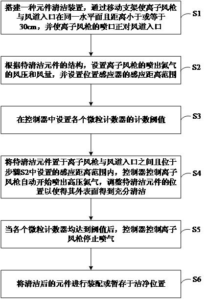
[0047] This embodiment provides a component cleaning method, comprising the following steps:
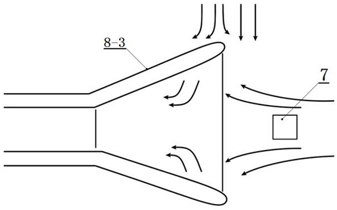
[0048] Step S1: Build the component cleaning device described in Example 1. By moving the bracket 5, the ion air gun 3 and the air duct inlet 8-4 of the horizontal section 8-2 are on the same horizontal plane with a distance of 30 cm. The nozzle of the ion air gun 3 Directly facing the air duct inlet 8-4 of the horizontal section 8-2.
[0049] The distance between the ion air gun 3 and the air duct inlet 8-4 can also be set to be less than 30cm, such as 20cm, which can also achieve better results.
[0050] Step S2: According to the structure of the component to be cleaned 7, set the air pressure and air volume of the nitrogen sprayed by the ion air gun 3, and set the sensing distance range of the position sensor 4.
[0051] For example, when the element 7 to be cleaned is an M8 stud with a length of 50 centimeters, the wind pressure can be set to 5 kg / cm2, the air volume is 800 stan...
PUM
 Abstract
Description
Claims
Application Information