Backlight and display

a backlight and display technology, applied in the field of backlight, can solve the problems of not giving a very good uniform emission, not revealing the nature of the “frosting", and not controlling the directionality of the light, so as to improve the desired viewing angle range of the display, reduce the cost, and reduce the effect of backligh

Inactive Publication Date: 2010-06-24
SHARP KK
View PDF22 Cites 53 Cited by
  • Summary
  • Abstract
  • Description
  • Claims
  • Application Information

AI Technical Summary

Benefits of technology

[0045]It is thus possible to provide a non-flat backlight whose angular light spread may be controlled so as to improve the desired viewing angle range of a display. This permits the use of a weaker diffuser and removes the need for any other brightness enhancing techniques in a plane in which the backlight is non-flat. In some applications, it may be possible to omit both of the conv

Problems solved by technology

This does not disclose the nature of the “frosting”.
The triangular structures are not taught to out-couple the light from the light-guide, and the “uniform” scattering arrangement of the light-guide would not in any case give a very good uniform emission.
The structures control the out-coupling of the light but do not control the

Method used


Image

  • Backlight and display
  • Backlight and display
  • Backlight and display

Examples


Embodiment Construction

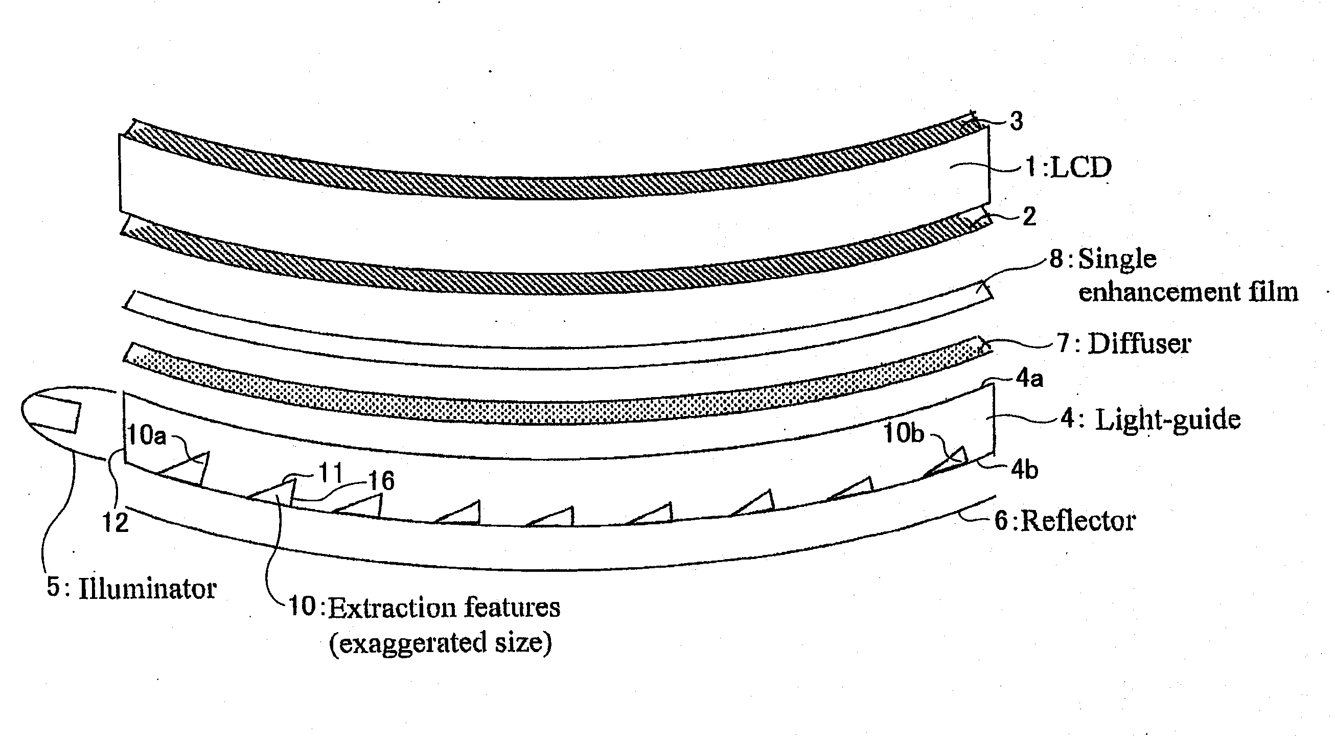
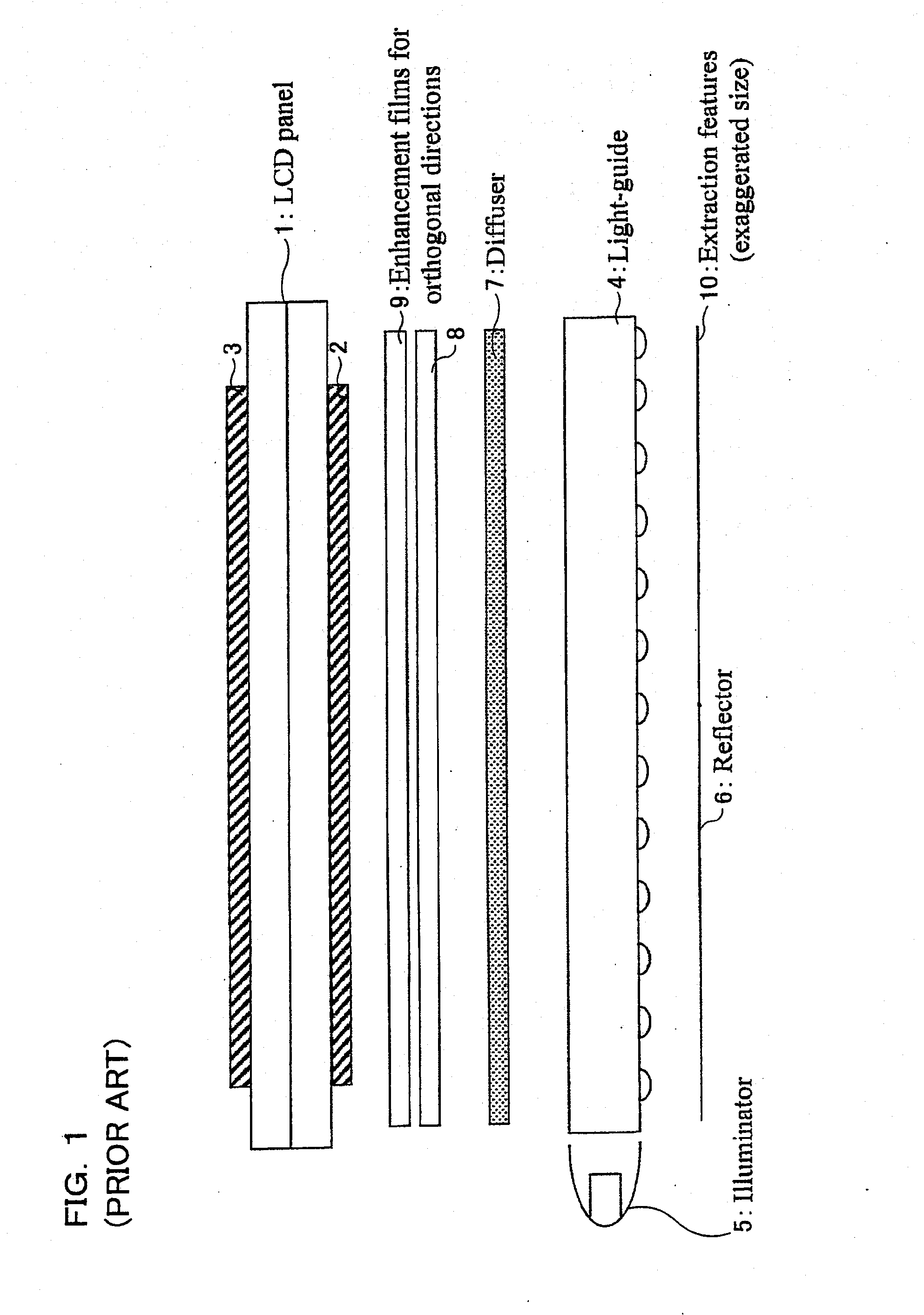
[0066]FIG. 3 illustrates a display which differs primarily from that shown in FIG. 1 in that the display is non-flat. In particular, in this embodiment, the display is curved about a single axis which is perpendicular to the plane of the drawing. Thus, the LCD 1 has an output surface which is cylindrically curved and is of substantially constant thickness. The input and output polarisers 2 and 3 are correspondingly curved, as are the light guide 4, the reflector 6, the diffuser 7 and the enhancement film 8. The display of FIG. 3 further differs in that the diffuser 7 is a weaker diffuser than that required in FIG. 1 and only a single enhancement film 8 is required. Further, the structure of the light guide 4 in FIG. 3 differs from that shown in FIG. 1. The display is concave in the sense that the image plane is concave when viewed from the viewing region in front of the display.

[0067]As shown to an exaggerated scale in FIG. 3, the extraction features 10 are concave features in the r...


PUM


Abstract

A backlight is provided for a transmissive spatial light modulator such as a liquid crystal device (1). The backlight comprises a light source (5), which supplies light through an input edge surface (12) of a non-flat light guide (4) having a front surface (4a) and a rear surface (4b). The rear surface (4b) comprises a plurality of concave features (10), each of which has a surface (11) which faces the input surface (12) and which is oriented so as to direct light towards and out of the front surface (4a). The surfaces (11) have slope angles with respect to a tangent plane to the rear surface (4b) at the feature (10) which vary with distance from the input surface (12) so as to concentrate output light from the light guide (4) into a desired angular output range.

Description

TECHNICAL FIELD[0001]The present invention relates to a backlight for an at least partially transmissive spatial light modulator. The present invention also relates to a display including such a backlight.BACKGROUND ART[0002]U.S. Pat. No. 4,616,295 (Hewlett Packard) describes a basic light-guide for display illumination (FIG. 1). It consists of a flat slab-type light-guide with two mounted fluorescent tubes, one at each end. The light-guide has “frosting” by which the light is coupled out. This does not disclose the nature of the “frosting”.[0003]U.S. Pat. No. 6,904,225 (Nichia) describes a pattern for the features that frustrate total internal reflection in the light-guide. This pattern is specific to point-like illuminators, such as LEDs, that do not illuminate evenly along the edge. This pattern increases the feature density between LEDs and decreases it near them to improve uniformity.[0004]JP 2006 / 066282 (Sharp) describes a flat slab-type light-guide with a fluorescent tube pos...

Claims


Application Information

Patent Timeline
IPC IPC(8): G02F1/13357
CPCG02B6/0038G02B6/0018
Inventor MONTGOMERY, DAVID JAMESROCARD, FLORIAN GILLES PIERRE
Owner SHARP KK
Why Eureka
Try Eureka