Pressure control structure for injection molding

A technology of pressure control and screw, which is applied in the field of pressure control structure for injection molding, can solve the problems that are difficult to realize, and can not be controlled by increasing the pressure of screw molten plastic, so as to achieve the effect of increasing production efficiency

Inactive Publication Date: 2021-04-20
吴剑飞
View PDF6 Cites 2 Cited by
  • Summary
  • Abstract
  • Description
  • Claims
  • Application Information

AI Technical Summary

Problems solved by technology

[0003] In the injection molding process, the granular or powdery plastic is first added into the barrel, and the plastic is melted by the rotation of the screw and the heating of the outer wall of the barrel, and then the screw injects the molten plastic into the mold cavity, but the current drive motor is driving the screw In the process of rotation, the speed of t

Method used


Image

  • Pressure control structure for injection molding
  • Pressure control structure for injection molding
  • Pressure control structure for injection molding

Examples


Embodiment Construction

[0023] The technical solutions in the embodiments of the present invention will be clearly and completely described below. The embodiments of the present invention and all other embodiments obtained by persons of ordinary skill in the art without making creative efforts belong to the protection scope of the present invention.

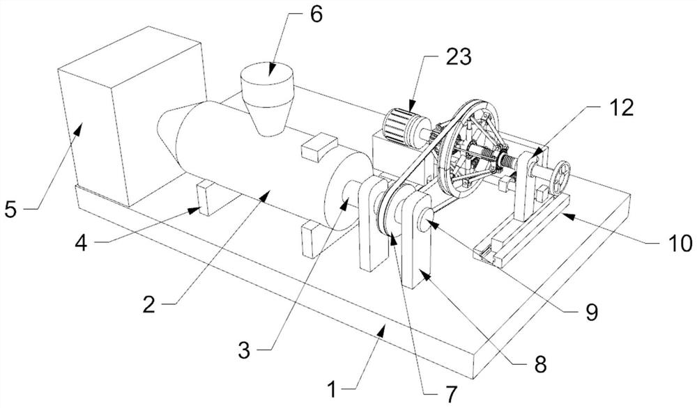
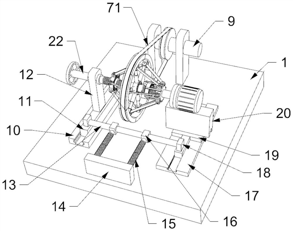
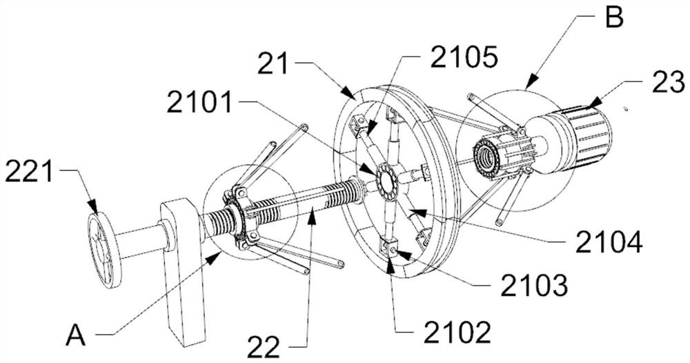
[0024] see figure see Figure 1 to Figure 5 , the present invention provides a technical solution: a pressure control structure for injection molding, including a screw 3, the screw 3 is installed in the barrel 2, the screw 3 is connected with a rotating shaft 9, and the rotating shaft 9 is installed on the first support column 8 On the top, the first support column 8 is vertically welded on the base plate 1, the rotating shaft 9 is equipped with a turntable 7, one side of the turntable 7 is provided with a speed change wheel 21, and the inside of the speed change wheel 21 is provided with a support device, the support device is formed by the first bear...


PUM


Abstract

The invention discloses a pressure control structure for injection molding. The pressure control structure comprises a screw rod, the screw rod is arranged in a machine barrel, the screw rod is connected with a rotating shaft, the rotating shaft is provided with a rotary disc, one side of the rotary disc is provided with a change wheel, the change wheel is internally provided with a support device, the support device is arranged on a threaded rod, and the two sides of the change wheel are provided with a driving device and a connecting device. By arranging the change wheel, when the screw rod needs to be accelerated, the radius of the change wheel can be increased, the rotating speed of the screw rod driven by the change wheel through the rotary disc can be increased, and the injection molding pressure can be controlled through the rotating speed of the screw rod, so that the production efficiency of injection molding can be improved; and by arranging the threaded rod, a first threaded cylinder and a second threaded cylinder, the first threaded cylinder and the second threaded cylinder can move forwards or backwards on the threaded rod through rotation of the threaded rod, stepless speed changing of the change wheel can be achieved, the rotating speed of the screw rod can be controlled at will through the change wheel, and then the injection molding pressure is controlled.

Description

technical field [0001] The invention relates to the technical field of injection molding devices, in particular to a pressure control structure for injection molding. Background technique [0002] Injection molding machine is also known as injection molding machine or injection machine. It is the main molding equipment for making thermoplastics or thermosetting plastics into various shapes of plastic products using plastic molding molds. Divided into vertical, horizontal, and all-electric types, the injection molding machine can heat the plastic and apply high pressure to the molten plastic to make it inject and fill the mold cavity. [0003] In the injection molding process, the granular or powdery plastic is first added into the barrel, and the plastic is melted by the rotation of the screw and the heating of the outer wall of the barrel, and then the screw injects the molten plastic into the mold cavity, but the current drive motor is driving the screw In the process of...

Claims


Application Information

Patent Timeline
IPC IPC(8): B29C45/77B29C45/58
Inventor 吴剑飞
Owner 吴剑飞
Why Eureka
Try Eureka