Camera installation with event camera
A camera device and event data technology, applied to cameras, focusing devices, installations, etc., can solve the problems of inaccurate acquisition of event data, light dispersion of measurement objects, etc.
- Summary
- Abstract
- Description
- Claims
- Application Information
AI Technical Summary
Problems solved by technology
Method used
Image
Examples
no. 1 approach
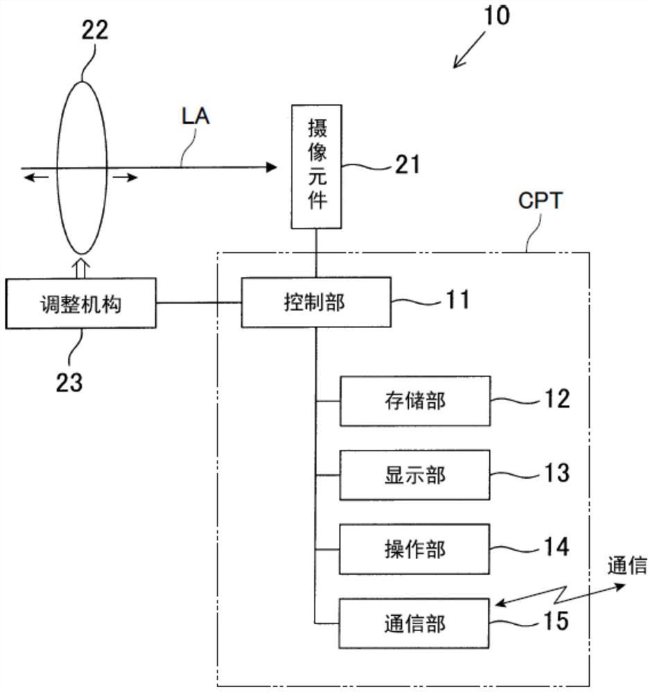
[0051] Below, refer to Figure 1 to Figure 6 , the first embodiment of the imaging device embodying the present invention will be described.
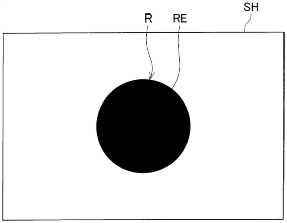
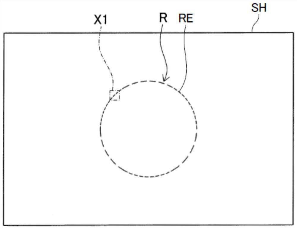
[0052] The imaging device 10 according to the present embodiment functions as a so-called event camera (Event Based Camera). This imaging device 10 is configured to detect event data including data for specifying the position of each pixel of a two-dimensional image having a brightness change, time, and the polarity (positive or negative) of the brightness change. Furthermore, this imaging device 10 is configured to create two-dimensional point data in which a plurality of event data outputted within a certain period of time are plotted on a given plane (predetermined plane), and to generate the two-dimensional point data as a photographed measurement image data of the object. In addition, the predetermined plane SH refers to a computationally two-dimensional plane set in the storage area of the storage unit 12 described later, and ...
no. 2 approach
[0090] Below, refer to Figure 7 ~ Figure 8 , the second embodiment of the imaging device embodying the present invention will be described.
[0091] In this embodiment and subsequent embodiments, the same or equivalent constituent elements as those of the imaging device according to the first embodiment are given the same reference numerals, and descriptions thereof are simplified or omitted.
[0092] The imaging device 10A according to this embodiment is also a device that functions as a so-called event camera, similarly to the imaging device 10 described above. This imaging device 10 outputs event data in a polarity manner including two-dimensional point data PD, time, and polarity of luminance change, including two-dimensional point data PD that specifies the position of the pixel corresponding to a pixel having a luminance change, and outputs multiple data within a certain period of time. The two-dimensional point data PD of each event data is plotted as points on a pred...
no. 3 approach
[0105] Next, refer to Figure 9A , Figure 9B as well as Figure 10A ~ Figure 10D , the imaging device according to the third embodiment will be described.
[0106] The imaging device according to the third embodiment itself has the same configuration as the imaging device 10A according to the second embodiment.
[0107] The present third embodiment differs from the above-described second embodiment mainly in that the above-mentioned predetermined threshold value is changed in accordance with the amount of shift detected by the phase difference AF sensor 25 . Therefore, the same code|symbol is attached|subjected to the structural part which is substantially the same as 2nd Embodiment, and the description is abbreviate|omitted.
[0108] also, Figure 9A It is an explanatory diagram showing an example of the object to be measured, Figure 9B is the description received from the Figure 9A In the case of the light of the measurement object, the explanatory diagram of the ch...
PUM
 Abstract
Description
Claims
Application Information
 - R&D
- Intellectual Property
- Life Sciences
- Materials
- Tech Scout
- Unparalleled Data Quality
- Higher Quality Content
- 60% Fewer Hallucinations
Browse by: Latest US Patents, China's latest patents, Technical Efficacy Thesaurus, Application Domain, Technology Topic, Popular Technical Reports.
© 2025 PatSnap. All rights reserved.Legal|Privacy policy|Modern Slavery Act Transparency Statement|Sitemap|About US| Contact US: help@patsnap.com


