A tower crane connection structure
What is Al technical title?
Al technical title is built by PatSnap Al team. It summarizes the technical point description of the patent document.
A connection structure and tower crane technology, applied in elevators, transportation and packaging, elevators in buildings, etc., can solve problems such as simple connection structure, poor safety, and affecting efficiency, so as to avoid manual climbing, avoid instantaneous impact, and expand good sex effect
Active Publication Date: 2022-06-17
LUOHE VOCATIONAL TECH COLLEGE
View PDF0 Cites 0 Cited by
Summary
Abstract
Description
Claims
Application Information
AI Technical Summary
This helps you quickly interpret patents by identifying the three key elements:
Problems solved by technology
Method used
Benefits of technology
Problems solved by technology
[0003] The operating room of the existing tower crane is mostly fixedly connected to the tower crane, and the connection structure is simple. It is directly fixed on the tower crane, causing the operator to manually climb up and down when moving up and down, which is very inconvenient and cannot effectively move the top and bottom. The transportation connection affects the efficiency and poor safety. At the same time, the structure of the existing upper and lower transportation devices is unstable, which leads to the inability to guarantee the safety of personnel moving up and down, and the expansion is poor.
Method used
Image
Click on the blue label to locate the original text in one second.
Reading with bidirectional positioning of images and text.
Examples
Embodiment Construction
[0024] The technical solutions in the embodiments of the present invention will be clearly and completely described below with reference to the accompanying drawings in the embodiments of the present invention. Obviously, the described embodiments are only a part of the embodiments of the present invention, rather than all the embodiments. Based on the embodiments of the present invention, all other embodiments obtained by those of ordinary skill in the art without creative efforts shall fall within the protection scope of the present invention.
[0025] In the description of the present invention, it should be understood that the terms "center", "upper", "lower", "front", "rear", "left", "right", "vertical", "horizontal", The orientation or positional relationship indicated by "top", "bottom", "inner", "outer", etc. is based on the orientation or positional relationship shown in the drawings, and is only for the convenience of describing the present invention and simplifying t...
PUM
Abstract
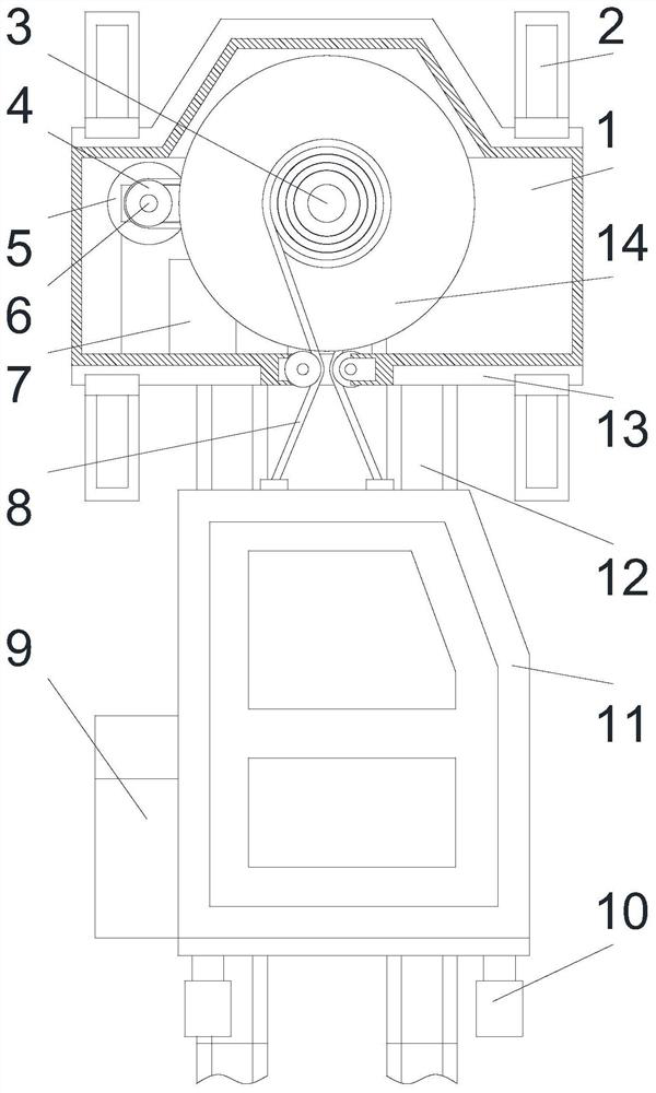
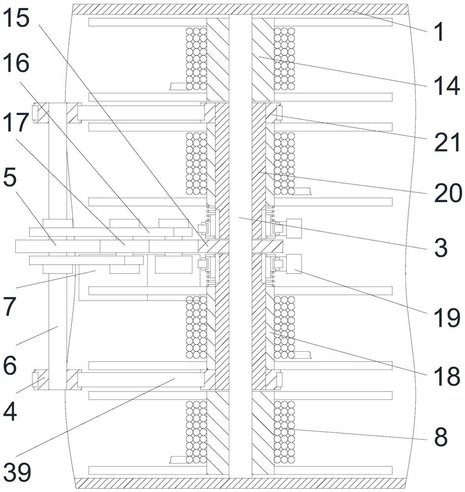
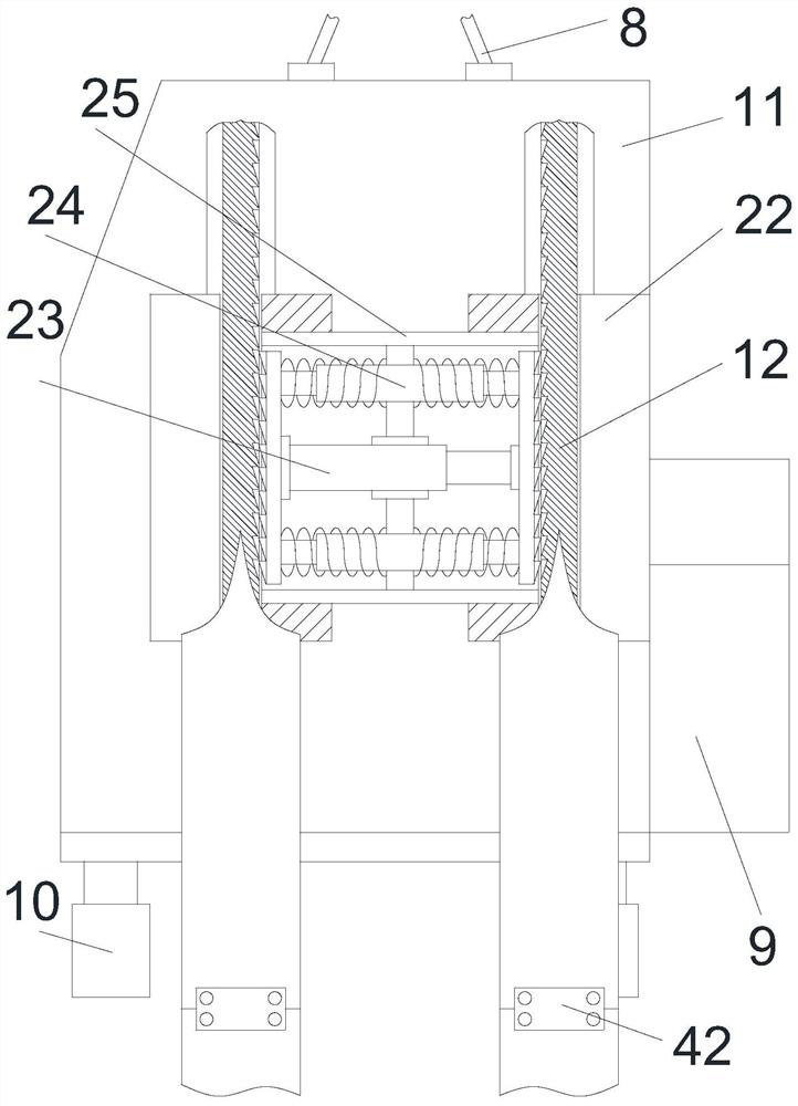
The invention discloses a tower crane connection structure, which mainly includes an outer frame, a side shaft, a motor, a steel cable, a control box, a car, a guide rail, an electromagnetic engaging frame, a sliding seat and a locking box, and the upper and lower ends of the outer frame are fixed A reinforcement frame is installed, and a symmetrical triangular bracket is fixedly installed on the edge of the reinforcement frame. The middle part of the inner side of the outer frame is rotatably installed with a central shaft, and the outer side of the central shaft is fixedly installed with a front and back symmetrical outer winding frame. A front and back symmetrical rotary sleeve is installed for rotation, and an inner winding frame is fixedly installed on the outer side of the rotary sleeve. The present invention is structurally designed reasonably, and through a flexible and reasonable connection structure, the car can move up and down for personnel transportation, has good expandability, adapts to the use environment of the tower crane, and has better safety, and has double lock shafts and reasonable The advanced anti-fall structure, through the soft and slow falling method, avoids the instantaneous impact of internal personnel when stopping, making it safer to use. At the same time, it is equipped with active steel cable detection to prevent problems before they happen.
Description
technical field [0001] The invention relates to tower crane equipment, in particular to a tower crane connection structure. Background technique [0002] Tower crane is the most commonly used lifting equipment on construction sites, also known as "tower crane". , concrete, steel pipes and other construction raw materials. The tower crane is an indispensable equipment on the construction site. The function of the tip of the tower crane is to bear the upper load from the jib pull rope and the balance arm pull rope, and pass the structure of the rotating tower, turntable, bearing seat, etc. The component type is directly transferred to the tower structure through the turntable. The top of the self-elevating tower has a truncated cone column type, a forward or backward truncated cone column type, a herringbone frame type and a diagonal support frame type. [0003] The operating room of the existing tower crane is mostly fixedly connected to the tower crane, and the connection...
Claims
Application Information
Patent Timeline
Application Date:The date an application was filed.
Publication Date:The date a patent or application was officially published.
First Publication Date:The earliest publication date of a patent with the same application number.
Issue Date:Publication date of the patent grant document.
PCT Entry Date:The Entry date of PCT National Phase.
Estimated Expiry Date:The statutory expiry date of a patent right according to the Patent Law, and it is the longest term of protection that the patent right can achieve without the termination of the patent right due to other reasons(Term extension factor has been taken into account ).
Invalid Date:Actual expiry date is based on effective date or publication date of legal transaction data of invalid patent.